Assignment 2#
Introduction#
In this assignment non-dispersive wave propagation and reflection/transmission of waves in a foundation pile, which is modelled as a bar (Figure 2), are considered. The theory was discussed in Lecture Topic 3 (model for the bar) and in Lecture Topic 8 (non-dispersive waves in an open channel).
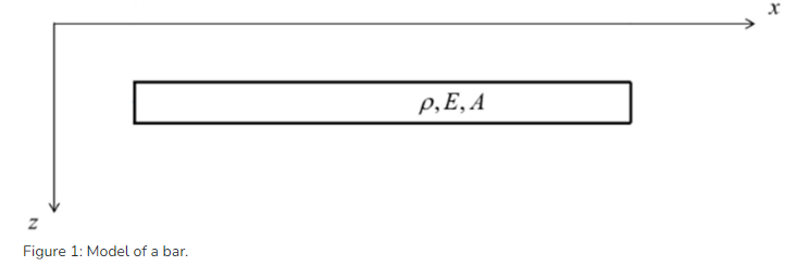
Fig. 2 Bar model#
The 1-D wave equation describes the wave propagation in the bar:
Here, \(\rho\), \(E\), \(A\) denotes the mass density, the Young’s modulus and the cross-sectional area of the pile, respectively while \(u_x\) denotes the longitudinal displacement.
Question 1#
Model answer
Since for the bar the double plane stress assumption was made (this is always the case if we have a bar), the stresses on the y face (as well as on the z face) are zero. Hence, answer “zero” is the correct one.
Question 2#
Model answer
We use the plane stress constitutive equations from Topic 3, so
Because of the double plane stress assumption, there is only uni-axial stress, so only axially loaded. Therefore, \(\sigma_{zz} = 0\)
For the longitudinal strain in \(z\) direction we can therefore write
Clearly, due the Poisson’s effect, the strains in out of plane directions are non-zero.
Eq.(3) is the sought-for answer.
Question 3#
Model answer
Look at and keep in mind that:
\(\sigma_{xx} = E\varepsilon_{xx}\) expresses the correct stress-strain relation for the case of double plane stress (“uni-axial stress”).
\(\sigma_{xx} = \frac{E}{1- \nu^2} \varepsilon_{xx}\) would be the right stress-strain relation for the case of plane stress and plain strain combined (i.e., for the diaphragm wall; see Lecture 3)
\(\sigma_{xx} = \frac{(1-\nu) E}{(1+\nu)(1- 2\nu)} \varepsilon_{xx}\) would be the right stress-strain relation for the case of double plain strain (“uni-axial strain”; see Assignment 1).
Solution to the 1-D problem of a Semi-infinite bar#
We consider the semi-infinite rod shown in Figure 3, which has free end at \(x=0\)
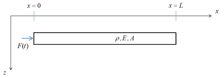
Fig. 3 Bar Model with Loading#
The transient excitation (hammer blow) is represented in the following simplified manner:
where \(t_0 = \frac{L}{4c}\) (i.e., the duration of the pulse is one quarter of the time it takes for a wave to propagate through the entire bar). We assume that the bar is initially at rest.
The general solution of Eq. 1 can be written as follows (D’Alembert’s solution):
where, \(u_x^+\) denotes a wave propagating in positive direction, and \(u_x^-\) in negative direction. Note that we are using the arguments \(t - \frac{x}{c}\) and \(t + \frac{x}{c}\) instead of \(x+ct\) and \(x-ct\), respectively (see also Topic 8). This is convenient when dealing with non-homogeneous boundary conditions.
Question 4#
Model answer
The expression for \(c\) can be determined by substituting the solution (Eq.(5)) into the equation of motion (Eq.(1)). We only demonstrate this for \(u_x^+\) (for \(u_x^-\) the same result is obtained in the same manner; it is allowed to do handle the solutions separately as Eq.(1) is linear and the superposition principle thus applies).
To determine the temporal and spatial derivatives of \(u_x^+\), we first define \(\tau = t - \frac{x}{c}\). Then,
By substituting these derivatives into Eq.(1), we find
This equation is satisfied provided that,
Eq.(8) is the sought-for answer.
Question 5#
Model answer
Starting from the relation between normal force and strain (i.e., the constitutive equation), we can determine the relation between \(u_x^+\left(t-\frac{x}{c}\right)\) and \(N^+\left(t-\frac{x}{c}\right)\):
Next, we use the fact that \(u_x^+\left(t - \frac{x}{c}\right)\) is constant when \(t - \frac{x}{c} = \mathrm{constant}\), that is, along
If \(u_x^+\left(t - \frac{x}{c}\right) = \mathrm{constant}\) along this line in the \(x\), \(t\) domain, it implies that its total time derivative is zero:
In the last step, the time derivative of Eq.(10) was used.
Now, Eqs.(9) and (11) can be combined to obtain
Eq.(12) (the last expression) is the sought-for answer.
Question 6#
Model answer
Starting from the relation between normal force and strain (i.e., the constitutive equation), we can determine the relation between \(u_x^-\left(t+\frac{x}{c}\right)\) and \(N^-\left(t+\frac{x}{c}\right)\):
Next, we use the fact that \(u_x^-\left(t + \frac{x}{c}\right)\) is constant when \(t + \frac{x}{c} = \mathrm{constant}\), that is, along
If \(u_x^-\left(t + \frac{x}{c}\right) = \mathrm{constant}\) along this line in the \(x\), \(t\) domain, it implies that its total time derivative is zero:
In the last step, the time derivative of Eq.(14) was used.
Now, Eqs.(13) and (15) can be combined to obtain
Eq.(16) (the last expression) is the sought-for answer.
Question 7#
Question 8#
Model answer
To answer this question, we need to determine the reflected wave based on the boundary coniditon at the free end. It reads
The Method of the Images can be employed to determine the reflected wave. It will be applied in terms of normal force and particle velocity as these quantities are one to one related (see Eqs. (12) and (16)). The Method of the Images is schematically illustraed in the figure below. The starting point is that a compression wave (as stated in the question; we assume for now an arbitrary shape and will determine the precise shape in the next question) propagates through the bar, as shown in the bottom left. Then, in order to respect the boundary condition (Eq. (17) at \(x = L\), the normal force associated with the image wave (which will be the reflected wave as soon as it enters the real domain) will have to have the same shape but opposite sign. Thus, the normal force changes sign during reflection. Hence, a compressional wave is reflected as a tensile wave (and vice versa). Thus the correct answer for the question is Tensile Wave.
Even though not asked, for completeness we note that the particle velocities corresponding with the incident and reflected waves can be determined using Eqs. (12) and (16). Clearly, the particle-velocity pulses have the same shape and also the same sign; see also question 10.
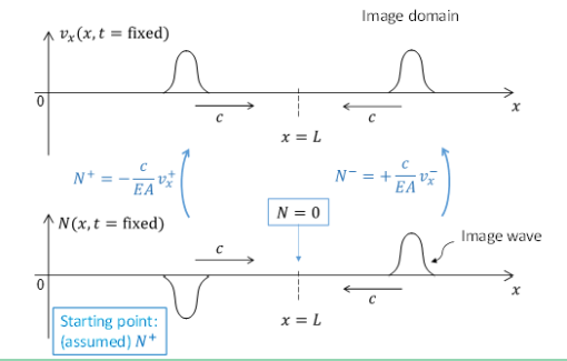
Fig. 4 Method of the Images#
Question 9#
Model answer
We determine the rightward propagating wave based on the boundary condition at \(x = 0\) (Eq.20FIGUREOUT). Using Eq.(12), we can write (assuming zero initial velocity)
With the known time signature of the particle velocity (Eq.(18)), the rightward propagating wave is essentially known throughout the entire bar as the wave is non-dispersive. Therefore, by introducing the following replacement, \(t \rightarrow t - \frac{x}{c}\), we obtain
To visualize the particle-velocity field spatially (ad in view of the application of the Method of the Images to determine the reflected wave; see later), we slightly rewrite this result:
Eq.(20) is the sought-for answer. The result in graphically represented in the figure below. Indeed the rightward propagating wave is a compression wave, as is clear from the corresponding normal force being negative. (Note that we have now derived this, while in the previous question we assumed the incident wave to be a compressional one)
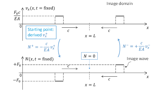
Fig. 5 Method of the Images#
Note that Eqs(19) and (20) are only valid for \(0<t<\frac{2L}{c}\). Beyond \(t = \frac{2L}{c}\) (the moment that the wave reflected from \(x = L\) has reached \(x = 0\)), a different expression for the rightward propagating wave would need to be found.
Question 10#
Model answer
The figure related to question 9 illustrates the rightward propagating wave as well as the image/reflected wave for the specific excitation. Using \(v_x(x = L, t) = v_x^+(x = L, t) + v_x^-(x = L, t)\) and the fact that \(v_x^-(x = L, t) = v_x^+(x = L, t)\), we find that the total particle velocity at the right end is doubled during reflection:
Eq.(21) is the sought-for answer.
We could have formulated an expression for the reflected wave (which originates from the image boundary \(x = 2L\)), but that is not really necessary for the required answer.
Question 11#
Model answer
The velocity associated with the rightward propagating wave has already been determined, see Eq.(19). The associated displacement can be found by direct time intergration (assuming zero initial displacement):
where, \(\tilde t\) denotes a time variable of integration. With the known time signature of the dispalcement, the displacement associated with the rightward propagating wave is essentially known throughout the entire bar as the wave is non-dispersive. Therefore, by again introducing the following replacement \(t \rightarrow t - \frac{x}{c}\), we obtain
To visualize the displacement field spatially, we slightly rewrite this result:
Clearly, \(u_x^+\) varies linearly in the interval \(c(t - t_0) < x < ct\), and the constant/’permanent’ displacment (i.e., behind the front) induce by the rightwad propagating wave is \(\frac{F_0 c t_0}{EA}\); see figure below.
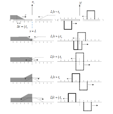
Fig. 6 Method of the Images#
The displacenent \(u_x^-\) associated with the reflected wave can be determined using the Method of the Images. It has to be chosen such that the boundary condition Eq(17) is satisfied at all times. Using the consitutive relation between normal force and displacement, the boundary condition is first written in terms of displacement:
Choosing the image wave such that it has the same shape as well as the same sign as \(u_x^+\) - see figure above - guarantee that the slope fo the total displacement is always zero, as required by Eq.(25); thus, the reflected wave has now been determined. The figure also illustrates the entire reflection process in terms of displacement (and normal force, for completeness).
Now, we can conclude that the ‘permanent’ displacement at \(x = L\) is doubled after reflection, and we find that
Eq.(26) is the sought-for answer.
We would like to make two remarks:
Note that the Method of the Images has now been applied in terms of displacement and normal force rather than in terms of particle velocity and normal force (as before).
Contrary to the relations between particle velocity and normal force (Eqs(12) and (16)), which are algebraic, the relations between normal force and displacement as obtained from the constitutive equation involce a spatial derivative:
Related to this, note that the displacement and normal force profiles related to both rightward and leftward propagating waves as shown in the figure above are in full correspondence with Eq.(27).
Question 12#
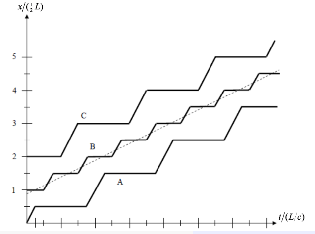
Fig. 7 Displacement Time History#
Model answer
The middle point of the bar is obviously initially located at \(\frac{x}{L} = \frac{1}{2}\). Hence, only line B can be correct. The first wave arrives in the middle at \(\frac{t}{L/c} = \frac{1}{2}\) (note that \(\frac{L}{c}\) signifies the time it takes for the wave to propagate once through the bar), and induces a linearly increasing displcement over the duration of \(t_0\), after which it becomes constant until the reflected wave arrives at \(\frac{t}{L/c} = \frac{3}{2}\). This wave also induces a linearly increasing displcement for the duration of \(t_0\) (see also figure related to question 11), after which the displacement again becomes constant. This behaviour is correctly represented by line B, and therefore the answer Line B is the correct answer.
The figure shows that no point of the rod moves continuously. On the contrary, every point experiences a “jerky motion”, which consists of the “rest phase” and the “movement phase”. In reality, however, there are effects like material damping, for example, that will smoothen such “jerky” motion of the rod particles. Specifically, curve B will approach (as time increases) the dashed line shown in the figure. Then, there will be no vibrations of the rod. Instead, each particle of the rod will have a constant translational velocity given by the slope of the dashed line (i.e., the bar will move as a rigid body).
Question 13#
Model answer
First, we need to determine what happens when the pulse reflected from \(x = L\) arrives at \(x = 0\) and gets reflected again. Since the excitation has disappeared by the time the pulse arrives at \(x = 0\), it experiences a free boundary:
Based on the Method of the Images, we can immediately determine the normal force \(N^+\) and the displacement \(u_x^+\) associated with the reflected wave such that Eq.(28) is respected; see figure below (the velocity profiles are included in the figure for completeness, although they are not necessary for the current question; also note that the ‘permanent’ displacement induced by the very first, rightware propagating wave, as shown in the figure related to question 11, is not included in the current figure). Clearly, the displacement pulse reflected from \(x = 0\) has the same sign as the incident wave (like for the reflection at \(x = L\)).
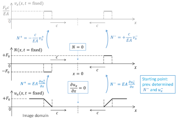
Fig. 8 Method of Images#
Now, at \(t = \frac{3L}{c}\), essentially three waves have passed (fully) the middle point, while the fourth one has not yet reached it. Therefore,
Eq.(29) is the sought-for answer.
Solution to the 1-D problem of junction of two semi-infinite bars with different properties#
We now consider the two semi-infinite rods connected as shown in Figure 9. As indicated, a wave travels in rightward direction. Clearly, this incident wave will generate a reflected and a transmitted wave at the interface. Taking all together, we can write
where \(u_i\), \(u_r\), \(u_t\) denote the amplitudes of the incident, reflected and transmitted pulses, respectively. The corresponding velocities are denoted as follows:

Fig. 9 Two Semi-infinite bars with different properties#
Question 14#
Model answer
The interface conditions entail the continuity of velocity (or displacement) and normal force, which can be written as follows using the relations \(N^{\pm}\left(t \mp \frac{x}{c}\right) = \mp \frac{EA}{c}v_x^{\pm}\left(t \mp \frac{x}{c}\right)\):
Eq(32) is the sought-for answer.
Question 15#
Model answer
The two relations in Eq.(32) can be used to determine \(v_t\) and \(v_r\) in terms of (the ‘known’) \(v_i\):
Hence, the transmission coefficient is found to be
Eq.(34) is the sought-for answer.
Note that the transmission coefficient is essentially defined here as the ratio of the two time-dependent functions. However, the result turns out to be time-independent (see right-hand side of Eq.(34)), which shows that the time signatures of \(v_t\) and \(v_i\) are the same. THis could have been expected as the interface conditions (Eq.(32)) must be satisfied for all moments in time, which can only be guaranteed if time signatures of \(v_i\), \(v_t\), and \(v_r\) are the same (their magnitudes are obviously different).
Question 16#
Model answer
For the specific case described, the expression for the transmission coefficient reduces to
Inserting \(A_1 = 0.10 \mathrm{m^2}\), one can easily compute that \(A_2 = 0.15 \mathrm{m^2}\).
