
10.2. Concrete - rules of thumb#
These ‘rules of thumb’ (Dutch: ‘vuistregels’) are to be seen as a quick way to estimate dimensions of structural members, based on span \(L\) and/or center-to-center spacing \(s\). These estimated dimensions should only serve as input for an early design stage calculation (e.g. first check of capacity or deformation), after which you will use more advanced design rules (e.g. Eurocode) for a more accurate calculation. Mind that you should not use them the other way around, as if the rules of thumb were some law that should be respected. They are just meant to get your design started.
Beam dimensions#
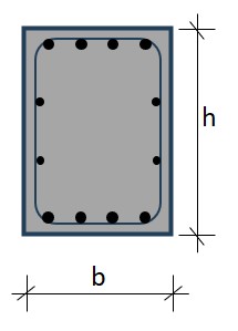
Fig. 10.2 Rectangular beams in cast on-site, traditionally reinforced concrete (= no prestress)#
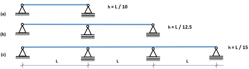
Fig. 10.3 Rules of thumb, traditionally reinforced concrete (= no prestress)#
Rules of thumb
Single span (beam on two support points, case a)
\(L = 2\) to \(20\) m
\(h = 200\) to \(2000\) mm
\(h = L/12\) to \(L/8\) \approx \(L/10\)
\(b = h/3\) to \(h/2\)
Multiple spans (continuous beam on 3 support points, case b)
\(h = L/15\) to \(L/10\) \approx \(L/12.5\)
Multiple spans (continuous beam on 4 support points or more, case c)
\(h = L/15\)
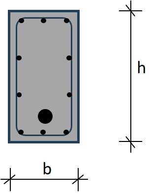
Fig. 10.4 Rectangular beams in cast on-site, prestressed concrete#
Rules of thumb
Single span (beam on two support points)
\(L\): same
\(h\): same
\(h = L/20\) to \(L/15\)
\(b = h/4\) to \(h/3\)
Multiple spans (continuous beam on 3 or more support points)
\(h = L/22\) to \(L/17\)
\(b = h/4\) to \(h/3\)
Beam bending reinforcement estimation - two methods#
- only for first estimation - later check \(\rho_{min}\) and \(\rho_{max}\) !
- for traditionally reinforced, not for prestressed concrete
- shear reinforcement not discussed here
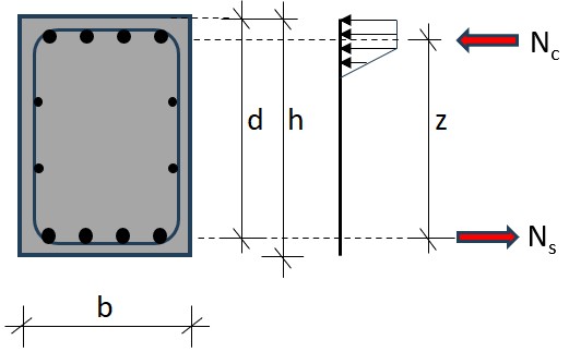
Fig. 10.5 Height h, effective height d and lever arm height z#
Method 1: ‘quick and dirty’ - use estimated height h
\(d \approx 0.9 h\)
\(z \approx 0.9 d \approx 0.81 h\)
\(A_{s;required} \approx \frac{N_s}{f_{yd}} = \frac{M_{Ed}}{z \cdot f_{yd}} = \frac{M_{Ed}}{0.81 \cdot h \cdot {435}} = \frac{M_{Ed}}{352 \cdot h} \frac{[Nm]}{[m]}\)
\(A_{s;required} \approx \frac{M_{Ed}}{0.35 \cdot h} \frac{[kNm]}{[m]}\)
NB mind the units: \(M_{Ed}\) in kNm and \(h\) in m!
This method can be used to verify if your chosen beam dimensions make sense. Check if \(A_s\) fits nicely in the cross-section and is proportional.
Method 2: more accurate - adjust h based on calculated bending moment and \(\rho=1\)%
step 1: estimate \(h\) and \(b\) using rules of thumb above
step 2: calculate \(M_{Ed}\) based on now available self weight and other loads
step 3: adjust \(d\) aiming for 1% reinforcement (=percentage considered economical optimum)
\(\frac{M_{Ed}}{b \cdot d^2} \le 4000\) (based on 1% bending tensile reinforcement)
(also here \(M_{Ed}\) in kNm and \(b\) and \(d\) in m)
\(\Leftrightarrow b \cdot d^2 \ge \frac{M_{Ed}}{4000}\)
with \(b \approx 0.5 \cdot d\):
\(\Rightarrow 0.5 \cdot d^3 \ge \frac{M_{Ed}}{4000}\Leftrightarrow d^3 \ge \frac{M_{Ed}}{2000}\)
solve \(d = \sqrt[3]{\frac{M_{Ed}}{2000}}\)
step 4: calculate \(A_{s;required}\) (which should indeed be \( \approx\) 1%)
\(z \approx 0.9 d \)
\(N_s = N_c = \frac{M_{Ed}}{z} \frac{[kNm]}{[m]} = [kN]\)
\(A_{s;required} = \frac{N_s}{f_{yd}} \frac{[N]}{[N/mm^2]} = [mm^2]\)
also here mind the unit changes
step 5: adjust \(h\) based on \(d\)
adjust \(h\) based on \(d\) + concrete cover c + 0.5 main reinforcement diameter + stirrup diameter:
\(h = d + c + 0.5 \cdot \) ⌀\(_{main}+ \) ⌀\(_{stirrup}\)
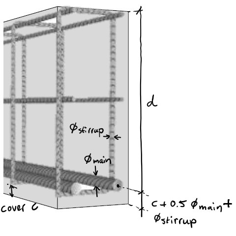
Fig. 10.6 Going from h to d#
step 6: iterate from step 2 onwards
- only if needed
- change in h leads to change in self weight G
- iteration only needed if G is proportionally a large contributor to ULS load
For shear reinforcement, prestressed concrete and further verification: use Eurocode
Floor thickness estimation (cast on-site)#
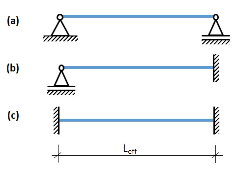
Fig. 10.7 Rules of thumb for thickness of cast in-situ floors, spanning in one direction (after: Constructieleer Gewapend Beton, 2008)#
For the support conditions shown in the figure above, the following approximation for effective floor height \(d\) can be used: (mind that \(d\) is not the floor thickness, but the effective height, similar to figure 10.6!)
For \(L_{eff} \le 7\) m:
case (a): \(d = L_{eff}/25\)
case (b): \(d = L_{eff}/32\)
case (c): \(d = L_{eff}/35\)
For \(L_{eff} > 7\) m:
case (a): \(d = L_{eff}^2/175\)
case (b): \(d = L_{eff}^2/225\)
case (c): \(d = L_{eff}^2/245\)
For floors that are spanning in two directions, either supported by beams, walls or columns, slightly different effective height equations should be used for a first approximation:
For \(L_{eff} \le 7\) m:
edge or corner floor field: \(d = L_{eff}/28\)
middle floor field (surrounded by other fields): \(d = L_{eff}/31\)
For \(L_{eff} > 7\) m:
edge or corner floor field: \(d = L_{eff}^2/195\)
middle floor field (surrounded by other fields): \(d = L_{eff}^2/215\)
For practical reasons the same floor thickness is often used throughout the whole floor area, unless much material can be saved by making the distinction. The latter is the case e.g. in large industrial floors with many intermediate supports in all directions.