
13.3. Foundation methods 2, pile foundations#
Introduction#
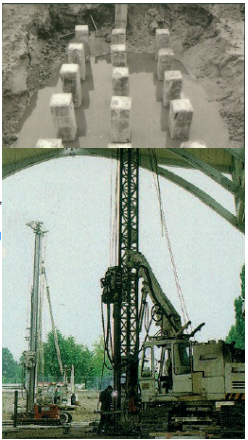
Fig. 13.2 Pile foundations.#
There are several criteria which need to be kept in mind when choosing a pile type:
the degree to which the surroundings are influenced by vibrations and noise
the degree to which the installation of the pile leads to soil deformations
the value of the foundation load and the type of loading (compression, tension, bending, static or dynamic)
demands on force-displacement behaviour
durability
difficulties during execution
costs
Each criterion has to be judged for each case separately. Execution aspects and difficulties are especially important. For example: a very weak soil can lack the strength to support the freshly casted concrete of a cast-in-place concrete pile (e.g. a vibropile). Another example: a wood pile cannot be driven 5 m into a sand layer without breaking. In the scheme on page fm4 the different pile types are sorted according to their application areas.
In general, driven piles lead to vibrations and noise in the direct surroundings. Therefore the first selection is usually based on the question whether pile driving is acceptable. This is important because driven foundations have important benefits over non-driven alternatives. For example:
driven systems can be calendered, which makes it possible to verify the assumed soil conditions during driving.
When driving a pile, it pushes aside the soil, thereby increasing strength and stiffness of the soil. The force-displacement behaviour is relatively stiff.
The pile shaft is relatively insensitive to the presence or absence of lateral soil pressure and groundwater flow.
Considerations#
Vibrations#
Pile driving can cause nuisance due to vibrations and even lead to damage to adjacent buildings. This damage is caused by the reduced strength of the soil beneath the adjacent building, induced by the deformation of this soil caused by the vibrations. Pile driving at a distance of 2 m does usually not give problems, but can cause nuisance (e.g. cracks in plasterwork). If there is a possibility of vibrations, deformation of the soil due to vibrations or compaction due to vibrations, vibration-free pile systems can be used. These contain several screwed systems and drilled piles. By means of an isolation sheet, a sound reduction of 5 dB(A) is possible.
Influence on surroundings#
While driving displacement piles, a temporary situation of perched water can occur which can lower the bearing capacity of adjacent foundations. Outside a circle with a radius of 8D (D= pile diameter) this effect is small. All screwed piles lead to a locally lower groundwater pressure. This relaxation can affect an area with a radius of about 4D to 6D. To keep the bearing capacity of existing piles intact, the cylinder of influence around the existing piles (about 2D) must remain undisturbed.
Pile length & transport#
All driven piles have a maximum length, dictated by the driving equipment. A typical maximum length is about 40 m, of which 5 m is reserved for the driving ram. The maximum therefore is about 35 m. For prefab piles, another limitation is the slenderness of the piles. This affects transport and drivability of the piles. A a rule of thumb: the slenderness of a pile (length/diameter) may not exceed 80. In urban areas, where access roads may be narrow, an additional limit to pile length may exist. This can reduce the maximum pile length to about 25 m.
Foundation tree#
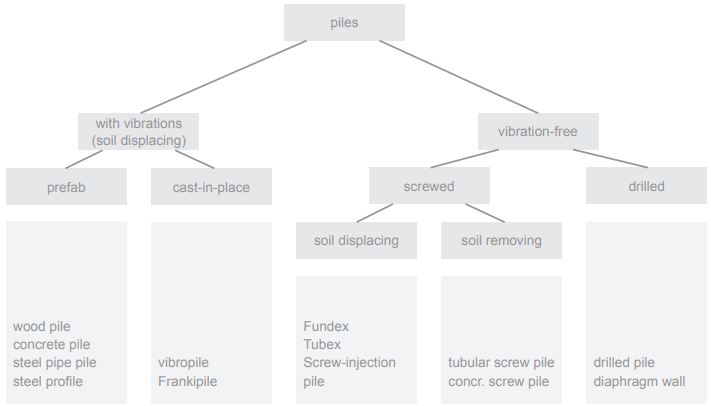
Fig. 13.3 Foundation tree#
Prefab concrete piles#
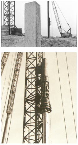
Fig. 13.4 Prefab concrete piles#
Information
Length: 2 - 32 m
Tip diameter: 150 - 500 mm
\(F_{s;d}\): 400 - 3000 kN
Explanation#
In practice for prefab piles shaft stress of no higher than 12 N/mm2 is chosen. This means that the maximum bearing capacity of a pile with a width of 450 mm at most is 2500 kN. Note that the soil conditions always determine the bearing capacity.
For standard foundations concrete of strength class C45/55 is used for piles 180 to 320. Prestress of 4 N/mm2 is commonly used. For heavy driving, for example in a 15 m sand layer, higher strength concrete can be used. Also the prestress is increased. Vibrations due to pile driving can lead to minor or major damage to adjacent buildings.
Features#
only smooth square shaft
design value of shaft bearing stress in practice no more than 12 N/mm2
concrete strength class: C25/30 to C50/60 with a prestress of 0 to 7 N/mm2
after driving the piles are broken at the head to enable the reinforcement of the pile to be connected to the structure.
piles are driven one by one
maximum angle approx. 1:3
age during driving >1 month
delivery time 2 months
common failures: broken pile or pile head
Application area#
high strength for both compression and tension
a lot of nuisance due to vibrations and noise
capable of handling large bending moments
stiff force-deformation behaviour
drivable to great depths (15 m) in compact sand (cone resistance 25 MPa)
Wood piles#
Information
Length: 5 - 15 m (or 7 - 20 m with concrete lengthening piece)
Tip diameter: 90 - 160 mm
\(F_{s;d}\): 150 kN
Explanation#
Wood piles are still very useful, provided that the pile heads are driven at least 0,5 m beneath the lowest possible groudwater table. Concrete lengthening pieces can be used to bridge the groundwater zone. Despite the possibilities, wood piles are not used frequently. The characteristic wood stress is mostly assumed to be 7 N/mm2. In practice the bearing capacity of wood piles is limited to 130 kN. Wood piles gain their strength trough both tip resistance and friction.
Features#
for foundations only round piles are used
whole pile must be driven at least 0,5 m beneath ground water table
ground water zone is bridged with concrete lenghtening pieces
taper of approximately 7,5 mm/m can be driven with a pile driver of 600 to 1200 kg.
Application area#
a lot of vibrations
stiff load-displacement behaviour
no tensile capacity
low bearing capacity
very flexible
pile lenght easy adjustable
cheap
only light equipment necessary
Steel tube piles#
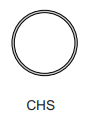
Fig. 13.5 CHS#
Information
Length: variable
Tip diameter: 114 - 813 mm
\(F_{s;d}\): up to 5000 kN
Explanation#
Suitable for application in areas with limited working height or space. Is able to resist large bending moments, also in soil retaining structures. Can be used in combination with sheet piles.
Features#
a steel tube, either with or without footing plate is driven into the soil
tubular segments can be welded to eachother on site, making this technique suitable in confined spaces
the tube is provided with reinforcement and filled with concrete. (this also gives corrosion protection)
besides the mentioned commercial sizes, special ordered (larger) dimensions are possible
Application area#
very large bearing capacity
able to take up large bending moments
can sustain heavy driving
suitable as tensile pile
suitable in confined spaces
Steel profiles (I, H and Z-profiles)#
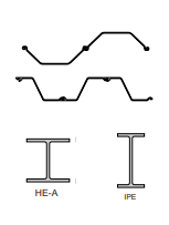
Fig. 13.6 Steel profiles (I, H and Z-profiles)#
Information
Length: variable
Tip diameter: variable
\(F_{s;d}\): variable
Explanation#
Designed as walls to resist horizontal forces in for example building pits and soil retaining structures. Can also be explanation used to resist vertical forces.
Features#
mostly in the shape of I-, H- or Z-profiles.
same features as steel tube piles, although open profiles cannot be filled with reinforced concrete, and they are less able to retain their shape
Application area#
can be coupled and used as water or soil retaining structure
limited drivability
suitable to take up tensile forces
Vibropile#
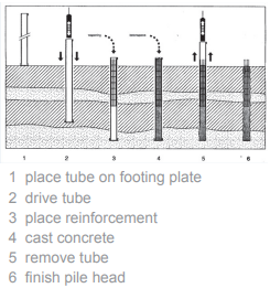
Fig. 13.7 Vibropile#
Information
Length: up to 35 m
Tip diameter: 273 - 610 mm
\(F_{s;d}\): 3000 kN
Explanation#
A steel tube with loose footing plate is driven in the soil. The tube is provided with reinforcement and filled with concrete. Before the concrete hardens the tube is removed either by driving or vibrating. The footing plate remains in the soil. For cast-in-place piles the stresses during driving are absent (as the actual pile is not driven). The concrete strength used is far less than the ones used for prefab piles. In practice shaft stresses of about 12 N/mm2 are used. This type also occurs as combi- pile, where a prefab pile is placed in the casing during casting.
Features#
fresh concrete must be sufficiently supported with small deformations
prestress possible
not possible on open water
angle possible
common failures:
necking of the shaft due to lack of support or driving to close to another fresh pile.
rock pockets
bleeding
Application area#
high bearing capacity
a lot or nuisance due to vibrations and noise
can take up large bending moments
stiff load-displacement behaviour
drivable up to 10 m in compact sand (cone resistance 20 MPa)
pile length easily adjustable
Frankipile#
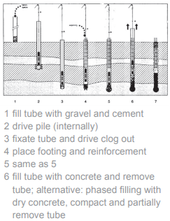
Fig. 13.8 Frankipile#
Information
Length: up to 25 m
Tip diameter: 324 - 610 mm
\(F_{s;d}\): 4000 kN
Explanation#
A steel tube is driven in the soil by hitting a cement clog inside the tube. When the desired depth is reached the clog is driven out by holding the pile in place. The shaft can be made out of concrete.
Features#
reinforced shaft possible
maximum diameter footing 2D (actual used dimensions are unknown)
common failures: same as Vibropiles
Application area#
high bearing capacity
less vibrations that vibropile
variable pile length
stiff load-displacement behaviour
suitable to take up tension forces
drivable as Vibro-pile
Fundexpile (steel tube pile)#
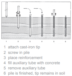
Fig. 13.9 Fundexpile#
Information
Length: up to 35 m
Tube diameter: 380/450/520 mm
Tip diameter: 450/550/650 mm
\(F_{s;d}\): 1500 kN
Explanation#
Fundex and Tubex piles are mostly applied when vibrations and soil relaxation (which causes bearing capacity reduction for nearby piles) is unwanted. Fundexpiles are made by screwing a steel tube with a loose tip into the soil. When the desired depth is reached the tube is provided with reinforcement and filled with concrete. Before the concrete hardens the tube is removed, also by screwing to avoid vibrations. The tip of the pile remains in the soil. A Fundexpile can be used up to 3 or 4 times in a sand layer.
Features#
a steel tube with a loose tip is screwed into the soil by applying an axial compression force and a torsional moment (max. approx. 400 kNm)
when the desired depth is reached the tube is provided with reinforcement and filled with concrete. The tube is removed vibration-free
placing under an angle is possible
Application area#
relatively high bearing force
almost vibration-free
little soil relaxation
pile tip level easily adjustable
Tubexpile (steel tube pile)#
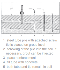
Fig. 13.10 Tubexpile#
Information
Length: up to 35 m
Tube diameter: 380/450/520 mm
Tip diameter: 450/550/650 mm
\(F_{s;d}\): 1500 kN
Explanation#
A steel tube with pile tip is screwed into the soil. When the desired depth is reached the tube is provided with reinforcement and filled with concrete. Both the pile and tip remain in the soil. If necessary, during screwing grout explanation can be injected.
Features#
A steel tube with screwtip welded to it is placed (placed identical as Fundexpiles)
When the desired depth is reached, the tube is filled with concrete and if necessary provided with reinforcement
during screwing, grout can be injected
placement under an angle is possible (max 1:1)
by welding short segments together on site, this pile is suitable for placement in confined spaces (min. working height approx. 2,5 m)
by injecting grout, the pile can be placed deep in the sand layer (approx. 7 m)
Application area#
little vibrations allowed
large bearing force needed (inject during installation)
very little soil relaxation
Augerpile#
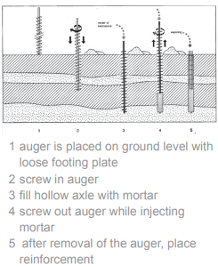
Fig. 13.11 Augerpile#
Information
Length: up to 20 m
Tip diameter: 300 - 900 mm
\(F_{s;d}\): 1000 kN
Explanation#
Auger piles are mainly applied in light structures where the foundation depth is not too great and no vibrations are allowed. Auger piles are made by screwing a hollow axle with an auger into the soil. If the desired depth is reached, the auger is screwed back and mortar is injected trough the hollow axle. After removal of the auger, a reinforcement cage is placed. Auger piles are not suitable for tension loads.
Diaphragm walls#
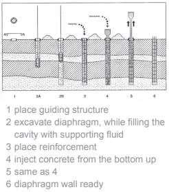
Fig. 13.12 Diaphragm walls#
Information
Length: more than 60 m
Tip diameter: up to 2400 mm
\(F_{s;d}\): 2-20 MN
Explanation#
For drilled piles, as a rule of thumb, the shaft stresses (at the connection between foundation and structure) are assumed to be not greater than 5 N/mm2. This is done to avoid large settlements. However, due to the large cross sections of the diaphragms very high loads are possible. Also tension loads can very well be taken by diaphragm walls.