10.5. Hollow core slabs#
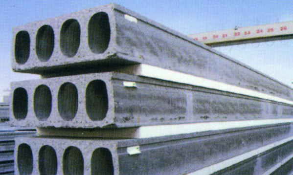
Hollow core slabs are prefabricated floor elements. The hollow plates are prestressed and arrive on site fully prefabricated. The hollow cores save a considerable amount of weight compared to the massive slab floor. The savings can be as much as 50%. This means that also the main bearing structure and foundation can be made considerably lighter 12.
The floor concept is based on the following principles:
No voids.
No concentrated loads.
Free supports (no clamped supports).
Standard fire resistance.
Deflection under variable load of max. 0,003 L.
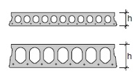
Fig. 10.12 Hollow core cross-section.#
Applications#
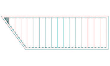
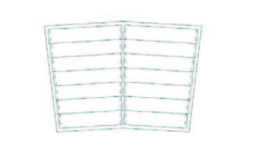
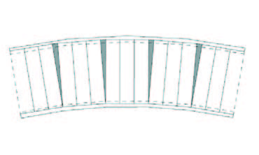
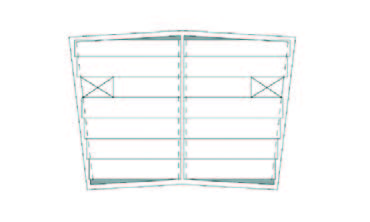
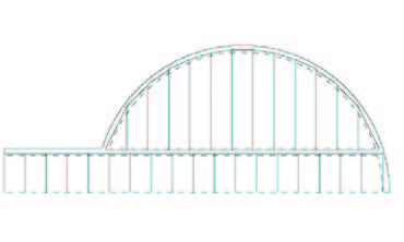
In contrast to what one may expect hollow core slabs also offer opportunities for free formed floor plans. The use of hollow core slabs is not restricted to the rectangular floor plans used in offices and flats. Both round shaps as chamfered egdes are possible. It is important to realise that the plates can be cut under an angle.
Execution aspects#
Small voids can be directly applied in prefabrication. The floor slabs can also be ordered with cast in light sockets and electricity ducts. When using hollow core slabs it must be noted that the prestress causes a precamber of the unloaded plate. This is mainly an issue with larger spans.
Rules of thumb for this precamber are:
1/1000 L with light prestress
3/1000 L with heavy prestress
Depending on the stiffness of the floor slab, the bearing and the levelness of the bearing the slabs can be supported in different ways:
directly on the underlying structure
in mortar
on fabric
on elastomeric strips
For variable loads to 3 kN/m2 and spans up to 6,5 m all support variants are possible. In other cases the elastomeric strips are recommended. The common bearing length is 100 mm in residential buildings, and 150 mm in non residential buildings.
To activate diaphragm action of the floors there are several option. In order of increasing load:
Mortar filled joints with added reinforcement.
Coupling of the plates to each other and the structure by means of extra reinforcement.
Application of a structural topping with a tensile tie coupled to the structure.
A combination of the aformentioned provisions with a cast-in peripheral beam which contains the tensile tie.
The horizontal loads from the floor are transmitted by concrete ‘studs’ to the stabilising elements of the building.
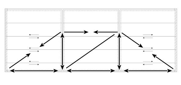
Fig. 10.14 Load transmission to stabilising elements.#
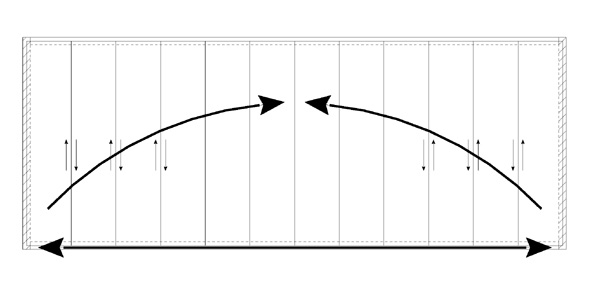
Fig. 10.15 Load transmission to stabilising elements.#
Product specifications VBI isolation slabfloor A200#
Property |
Value |
|---|---|
Weight including joint mortar |
303 kg/m² |
Fire resistance |
60 - 90 minutes |
Maximum slab length |
|
- non-residential buildings |
10.00 m |
- floor residential buildings |
7.60 m |
- roof residential buildings |
9.00 m |
Filler slabs width |
|
- residential |
300 + n x 100 mm (AL200) |
- non-residential |
300 + n x 150 mm |
Joint mortar |
7.3 l/m |
Strength class |
C45/55 |
Cross section |
144623 mm² |
Center of gravity |
99.3 mm |
Moment of inertia |
680.0 E+06 mm⁴ |
Use of recycled concrete granule |
20% on request |
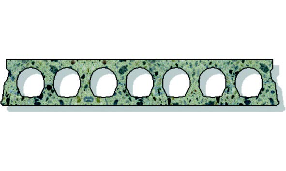
Fig. 10.16 VBI A200 slab floor cross-section.#
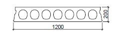
Fig. 10.17 Dimensions of VBI A200 slab floor.#
Spans#
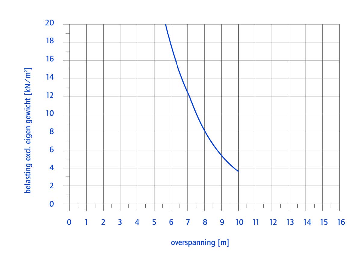
Fig. 10.18 Load resistance vs. spans of a Hollow Core slab (VBI 200).#
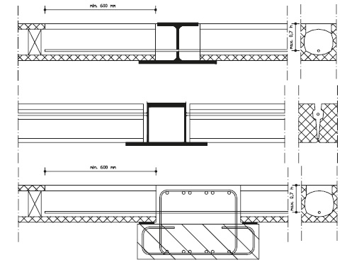
Connections (All types of hollow core slabs)#
The bearing length ‘a’ should, when a SBR centering strip is used, fulfill the following conditions:
\(L\) = span in mm.
\(a = a_r + a_o\)
\(a_o\) = see figure
\(a_r\) = distance from edge of supporting member to edge of bearing, for \(a_r\), a value no larger than \(25 mm\) can be used. Preferably it is exactly \(25 mm\).
SBR centering strips centering strips have different functions, depending on their application:
centering the load;
prevent the slabs from shifting;
preventing or limit clamping moments.
Centering strips are used in different situations:
when the floor is clamped;
for bearings on concrete and masonry;
for bearings on a steel substructure where the load needs to be centered.
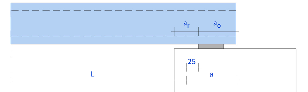
Fig. 10.19 Minimum conditions for the bearing length of a Hollow Core slab.#
Product specifications VBI isolation slabfloor A320#
Property |
Value |
|---|---|
Weight including joint mortar |
443 kg/m² |
Fire resistance |
90 - 120 minutes |
Maximum slab length |
14.70 m |
Filler slabs width |
300 + n x 150 mm |
Joint mortar |
11.9 l/m |
Strength class |
C45/55 |
Cross section |
209918 mm² |
Center of gravity |
153.8 mm |
Moment of inertia |
2568.1 E+06 mm⁴ |
Top surface |
Normal or rough |
Use of recycled concrete granule |
20% on request |
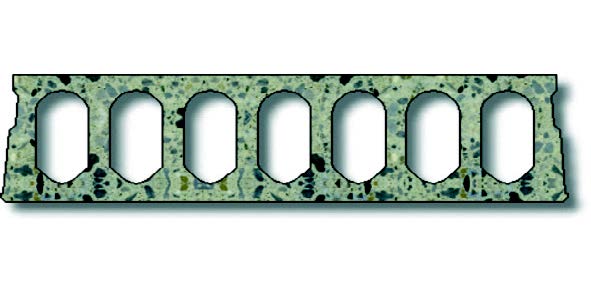
Fig. 10.20 VBI A320 slab floor cross-section.#
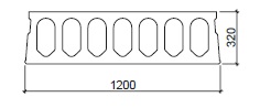
Fig. 10.21 Dimensions of VBI A320 slab floor.#
Spans#
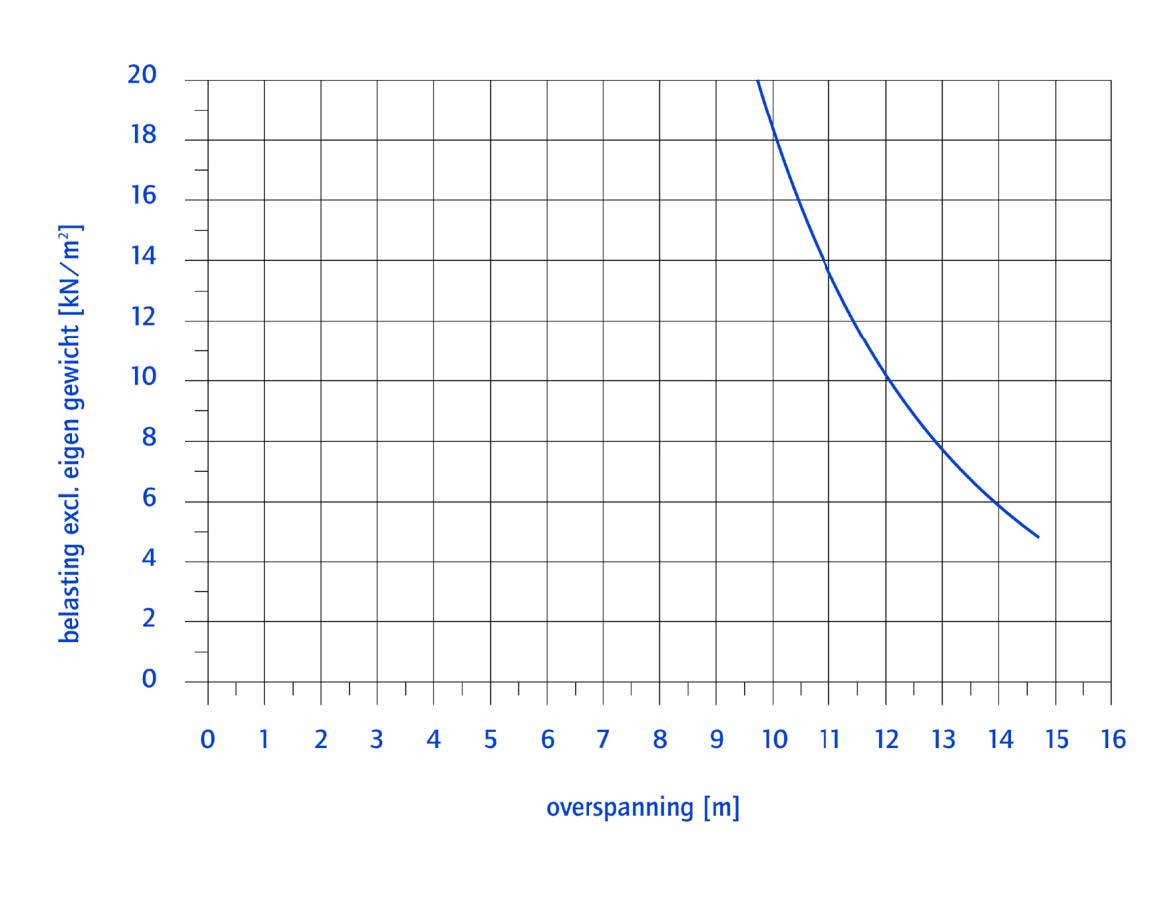
Fig. 10.22 Load resistance vs. spans of a Hollow Core Slab (VBI 320).#
Connections (All types of hollow core slabs)#
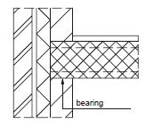
Fig. 10.23 Support on cavity wall#
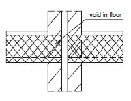
Fig. 10.24 For walls separating two houses the hollow cores near voids are filled with mortar, mineral wool of polymer foam.#
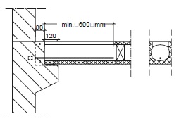
Fig. 10.25 Bearing on console#
Product specifications Dycore hollow core slabs#
Property |
Value |
|---|---|
Fire resistance |
60 - 90 minutes |
Density |
2400 kg/m³ |
Prestressing Steel |
FeP 1860 |
Type |
Height \([mm]\) |
Weight \([kN/m²]\) |
Joints \([l/m]\) |
Cross Section \([mm^2]\) |
Filler slabs min. Width \([mm]\) |
Max. Length \([m]\) |
|---|---|---|---|---|---|---|
W |
150 |
2.4 |
4.4 |
0.11 |
297 |
6 |
N |
200 |
2.7 |
5.7 |
0.13 |
643 |
9 |
U |
200 |
3.1 |
5.7 |
0.15 |
666 |
9 |
T |
255 |
3.7 |
7.2 |
0.17 |
1364 |
12 |
H |
320 |
4.3 |
8.7 |
0.20 |
2517 |
15 |
K |
400 |
5.0 |
10.9 |
0.23 |
4625 |
18 |
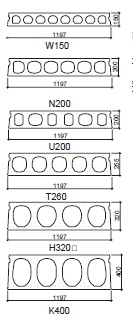
Fig. 10.26 Different cross-sections of Dycore Hollow Core Slabs.#
Spans#
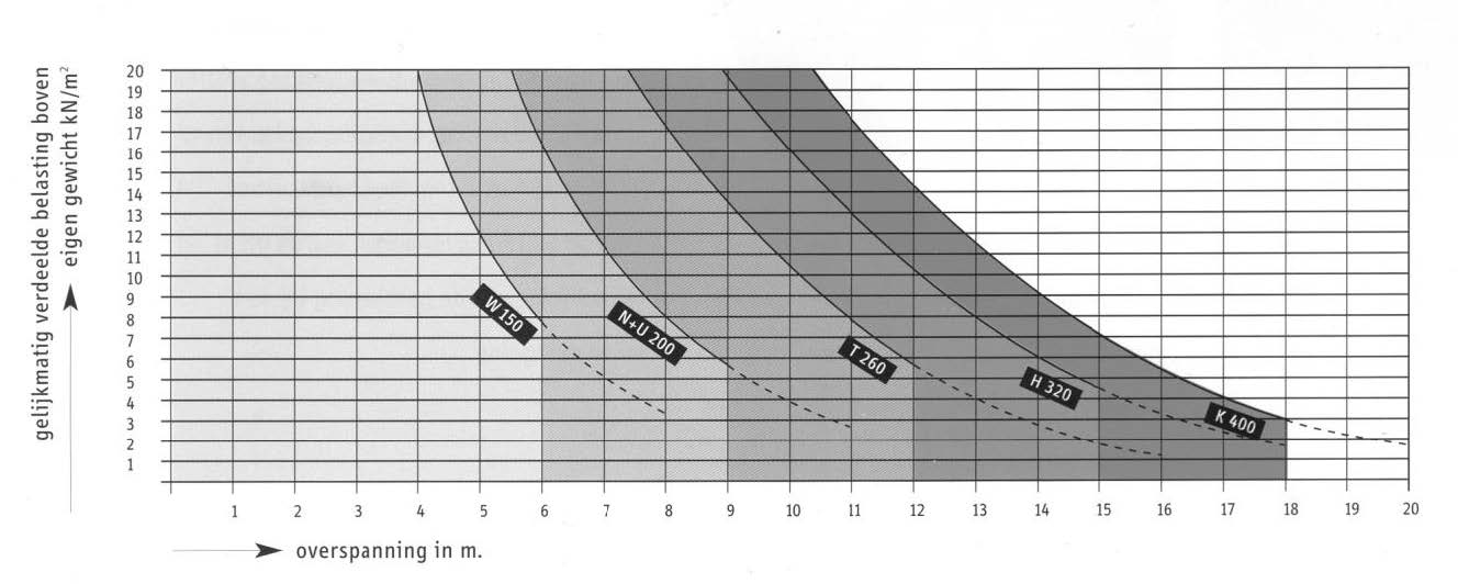
Fig. 10.27 Load resistance vs. span Hollow Core Slab (Dycore).#
Note
The graph indicates the maximum distributed load (excluding self weight) for different spans for slabs on two supports
Connections (All types of hollow core slabs)#