
17.2. Global dimensioning column#
Note
The calculations serve as examples for educational purposes and not as guidance for practice.
Estimation rules also exist for columns, but especially for these elements, the actual dimensions required can be very different from those found with these estimation rules. The dimensions of the column depend strongly on the buckling length. However, there is a big difference whether a column has to support an entire building with many floors or just the roof. Often, the column at ground level is the ‘dimensional’ column. A slender column with large buckling length could also be normative, even if it is not on the ground floor.
Note that for the b and for the I, the weakest direction should always apply: For HEA profiles, we therefore do not take the profile height but the width of the profile and \(I_z\). Precisely this direction is the weakest and (usually) determines buckling out.
We are going to dimension and check column D3 under the 1st floor for the office. To perform the check, we need to know what load the column has to bear. To do this, we first create a load diagram and then a weight calculation that we tabulate.
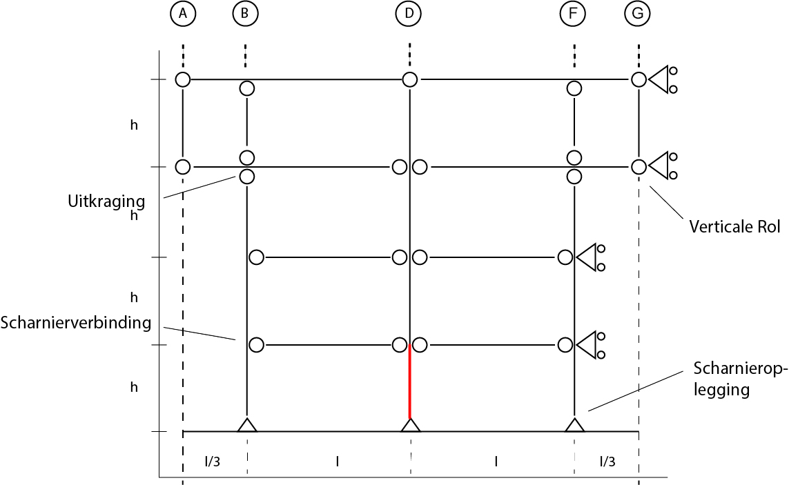
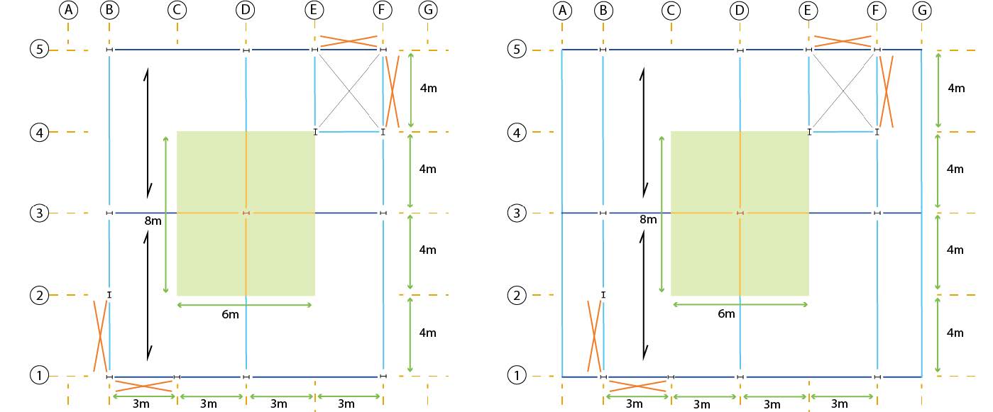
The load diagram consists of all schematic DC plans (or a 3D drawing) showing the column in question and all structural members resting on it: Columns and beams possibly by colour and the floor area by shading. All beams within the shaded areas transfer their load to the column. We also show the length dimensions so that the total load to be carried by the column can be easily determined. The load diagram also includes collecting the loads on the column.
Note
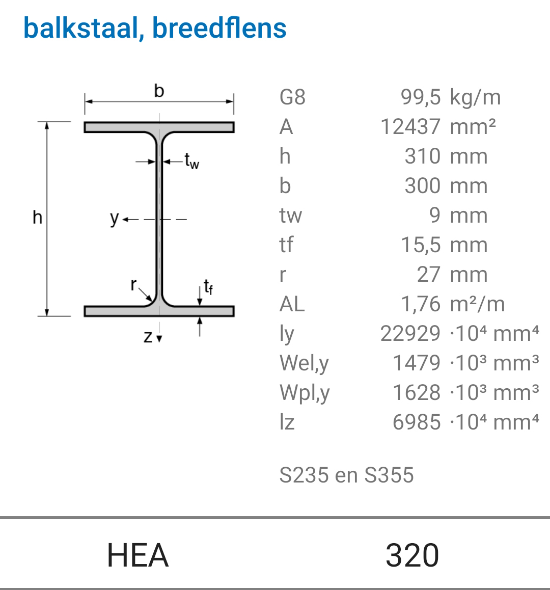
The imposed load on the beam and the superimposed load have already been determined in the beam’s verification calculation. We found \(3\) for the imposed floor load and \(4.9 [kN/m^2]\) for the superimposed load on the beam. We will use the beams identified in the verification calculation. For the steel structure, this was an HE300A, strength class S355, with a weight of \(0.88 [kN/m]\).
For simplicity, we assume that the permanent load of the roof is equal to that of the floors. The roof beams are the same as those in the floor. Depending on the roof covering, the difference will not be significant. According to the Eurocode, for a roof not used as a terrace, an imposed load of \(1 [kN/m^2]\) should be taken for every \(10 [m^2]\) of roof area. For the entire roof, a lower imposed load can be considered. However, we choose an imposed load of \(1 [kN/m^2]\). This also provides the option for installing solar panels (PV panels) or adding a light sedum planting. It is advisable to consistently record the data found for clarity. The table below summarises the loads.
Imposed Load |
Imposed Load |
Resting Load |
Resting Load |
Beam Weight |
Beam Weight |
|
|---|---|---|---|---|---|---|
Floor |
Roof |
Floor |
Roof |
Floor |
Roof |
|
[kN/m²] |
[kN/m²] |
[kN/m²] |
[kN/m²] |
[kN/m] |
[kN/m] |
|
Steel Frame |
3 |
1 |
4.9 |
4.9 |
0.88 |
0.88 |
Note
The steel structure uses HEA profiles for the columns. The most heavily loaded column is the central column on the ground floor.
Using the estimation rules, we roughly determine the dimensions the column should have.
In the Steel Profiles App, we search for the corresponding profile and note down the details.
Weight table#
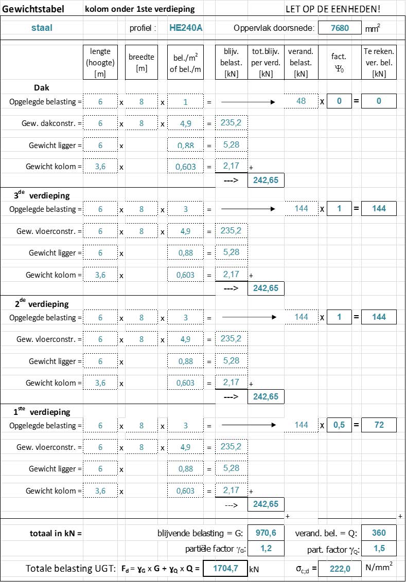
The load is schematically represented as a point load on the column. All loads must therefore be converted to a load in kN. This can be done systematically with a weight table. This table calculates all loads on the column, per floor. The following pages show a weight table for the steel and the concrete column.
The weight of columns and beams (given in kN per m) must be multiplied by the respective floor height and beam length to obtain a point load: [kN/m] \(\Rightarrow\) [kN].
The imposed load and the permanent floor load are determined in [kN/m^2]. Therefore, they must be multiplied by the area in [m^2] that is supported by the respective column: [kN/m^2] \(\Rightarrow\) [kN]. To facilitate calculation, we’ll place the table in an Excel spreadsheet as shown in the figures below.
According to the standard committee, the probability of all floors being extremely loaded is almost nil. Therefore, for the variable load, the combination factor \(\psi_0\) (formerly called the moment factor) has been introduced. This is a reduction factor that should be used for almost all floors except two.
For the two floors that contribute the most to the variable load, this should be taken extremely (\(\psi_0=1\)).
For the other floors, \(\psi_0\) depends on the use of the floor. For offices, according to the National Annex to the Eurocode, \(\psi_0 = 0.5\). For the roof, \(\psi_0 = 0\) can even be taken (but not if we consider the column under the roof or under the top floor). The formula for the total load on the column is:
\(\gamma_{G}\) and \(\gamma_{Q}\) are the (partial) safety factors.
Control calculation column (compressive strength)#
From the column, we will verify the compressive strength and determine the slenderness ratio \(n\).
For the compressive stress, we have:
Where:
\(A\) is the cross-sectional area.
\(f_{c;d}\) is the compressive strength.
We can also perform the Unity Check here:
If the strength is not satisfied, then we can multiply the found \(A\) by the value of the Unity Check to obtain the required cross-section:
Note
For the steel column, the total load on the column according to the weight table is 1705 [kN]. The stress in the column is:
\(\sigma_{c;d} = \dfrac{F_{c;d}}{A} = \dfrac{1704.7 \cdot 10^3 [N]}{7680 [mm^2]}= 222 [N/mm^2]\)
The Unity Check for the HE240A profile can be determined:
\(U.C. \Rightarrow \dfrac{\sigma_{c;d}}{f_{c;d}}=\dfrac{222 [N/mm^2]}{235 [N/mm^2]}=0.94 < 1.0 \Rightarrow \textcolor{green}{\text{Meets Requirement}}\)
Determination of buckling number n#
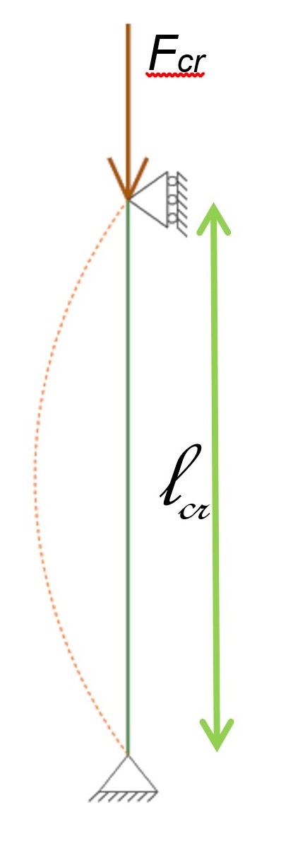
Buckling is a dangerous form of failure that occurs quite suddenly. This problem was recognised long ago. In 1744, the Swiss scholar Leonard Euler came up with the following formula:
\(F_{cr}\) (or \(F_E\)) is called the Euler or critical buckling force.
E represents the modulus of elasticity. For concrete and wood, the modulus of elasticity for UGT should be applied, for concrete \(E_{c,d}\), and for wood \(E_{0,05}\) or, for laminated wood, \(E_{0,gl,05}\).
\(I\) is the quadratic surface moment in the weakest direction!. The weak direction is indicated in the Netherlands with the z in the caption because the weak bending direction is around the z-axis: \(I_z\).
\(l_{cr}\) is the buckling length. In a braced building with hinge connections between columns and beams, the buckling length of the column is equal to the floor height.
Note
For a column of a HE240A profile, we have:
\(F_{cr} = \dfrac{pi^2 \cdot E \cdot I_z}{l^2_{cr}}=\dfrac{\pi^2 \cdot 210000 [N/mm^2] \cdot 27.69 \cdot 10^6 [mm^4]}{(3600 [mm])^2}= 4428.3 \cdot 10^3 [N] \)
\(n = \dfrac{F_{cr}}{F_{c;d}}= \dfrac{4428.3 \cdot 10^3 [N]}{1705 \cdot 10^3 [N]} = 2.6 < 5 \)
\(U.C. \Rightarrow \dfrac{5 \cdot F_{c;d}}{F_{cr}}=\dfrac{5 \cdot 1705 \cdot 10^3 [N]}{4428.3 \cdot 10^3 [N]}= 1.92 > 1 \Rightarrow \textcolor{red}{\text{Does not meet requirement}}\)
The buckling number is too small, indicating insufficient safety. A larger profile is needed:
\(I_{z,necessary} = U.C. \cdot I_{z,old} = 1.92 \cdot 27.69 \cdot 10^6 [mm^4] = 52.6 \cdot 10 [mm^4]\).
In the steel profile app, a profile with at least this quadratic surface moment can be found. This could be, for example, a HE300A, which provides sufficient buckling safety. A higher strength class is not meaningful here.