
12.2. Timber structures and details#
Straight beam (possibly with precamber)#
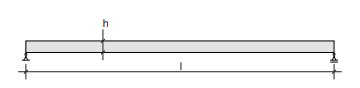
Fig. 12.2 Straight beam (possibly with precamber).#
Rules of thumb
Solid timber beams
\(l = 2 - 6 m\)
\(h = \frac{l}{15} - \frac{l}{20} m\)
Glulam (=glue-laminated) beams
\(l = 6 - 30 m\)
\(s < 5 m \rightarrow h = \frac{l}{17}\)
\(s = 5 - 8 m \rightarrow h = \frac{l}{16}\)
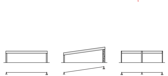
Fig. 12.3 Possible shapes.#
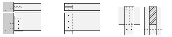
Fig. 12.4 Details (left: support on continuous column; middle: support on concrete wall; right: support on double timber column (by means of support block)).#
Straight beam (possibly with cantilever)#
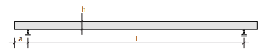
Fig. 12.5 Straight beam (possibly with cantilever).#
Rules of thumb
Glulam beams
\(l = 30 m\)
\(s = 3.6 - 5.4 m\)
\(a = 0.25 \cdot l \rightarrow h = \frac{l}{16} - \frac{l}{21}\)
\(s = 3 - 5 m\)
\(a = 0.4 \cdot l \rightarrow h = \frac{l}{18} - \frac{l}{24}\)
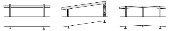
Fig. 12.6 Possible shapes.#
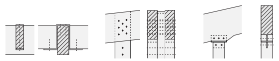
Fig. 12.7 Details (left: support of purlins on main beam by means of Z-profile; middle: double beam on a double timber column (bolted); right: beam on timber column, with steel connector plate (bolted)).#
Saddle roof with inclined upper edge#
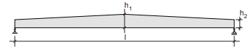
Fig. 12.8 Saddle roof with inclined upper edge.#
Rules of thumb
Glulam beam
\(l = 6 - 30 m\)
\(h_1 = \frac{l}{14} - \frac{l}{18}\)
\(h_2 = \frac{l}{18} - \frac{l}{22}\)
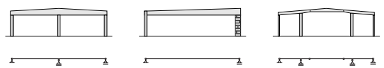
Fig. 12.9 Possible shapes.#
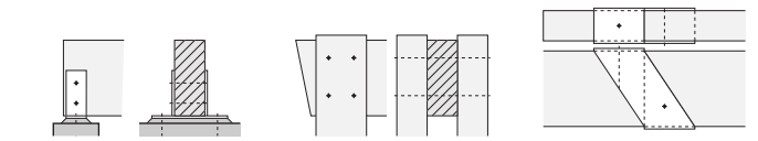
Fig. 12.10 Details (left: beam on wall, welded steel connection; middle: connection between beam and double column (bolted); right: beam-beam connection with steel connector plate (Dutch: gerberligger)).#
Saddle roof with inclined or curved upper and lower edge#
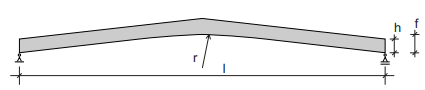
Fig. 12.11 Saddle roof with inclined or curved upper and lower edge.#
Rules of thumb
Glulam beams
\(l = 7 - 40 m\)
\(s = 5 - 7 m \rightarrow h = \frac{l}{14} - \frac{l}{18}\)
\(f = \frac{l}{5} - \frac{l}{10}\)
\(r \geq 6 m\)
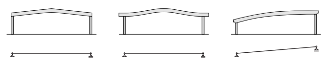
Fig. 12.12 Possible shapes.#
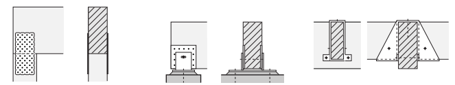
Fig. 12.13 Details (left: beam-column connection (nailed plates); middle: support on wall, full hinge with slotted hole (screwed steel plate); right: purlin-beam connection with steel connector, load acts on top of main beam).#
The upper edges need lateral support.
Warning
The curved shape causes tension pependicular to the grain.
Continuous beams#
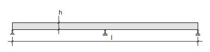
Fig. 12.14 Continuous beam.#
Rules of thumb
Glulam beams
\(l = 6 - 30 m\)
\(s < 5 m \rightarrow h = \frac{l}{34}\)
\(s = 5 - 8 m \rightarrow h = \frac{l}{30}\)
Glulam trusses
\(l = 10 - 80 m\)
\(s = 2 - 5 m \rightarrow h = \frac{l}{16} - \frac{l}{18}\)
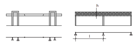
Fig. 12.15 Possible shapes.#
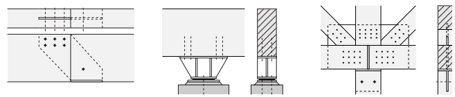
Fig. 12.16 Details (left: beam-beam connection with steel connector plate; middle: heavy support (welded); right: truss connection (with column) wih coupler plate and dowels).#
The upper edges need lateral support.
Straight truss#
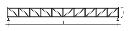
Fig. 12.17 Straight truss.#
Rules of thumb
Solid timber
\(l = 5 - 25 m\)
\(s = 2.5 - 6 m \rightarrow h = \frac{l}{10} - \frac{l}{14}\)
Glulam
\(l = 20 - 80 m\)
\(s = 2.5 - 6 m \rightarrow h = \frac{l}{10} - \frac{l}{15}\)
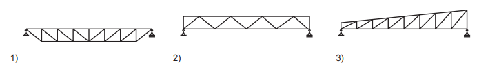
Fig. 12.18 Possible shapes.#
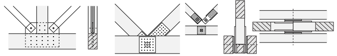
Fig. 12.19 Details (left: connection of tensile bars (steel strips) to bottom chord and compressive strut (coupler plate); middle: connection between bottom chord and diagonals with screwed steel plates and central axle; right: connection between bottom chord and diagonals with screwed steel plates and central axle).#
The upper chords (under compression) must be supported laterally in all trusses. For truss type 1 the bottom chord also needs lateral support to prevent the tensile chord from twisting out of plane.
Triangular or trapezoidal truss#
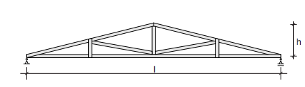
Fig. 12.20 Triangular or trapezoidal truss.#
Rules of thumb
Glulam beam
\(l = 7.5 - 30 m\)
\(s = 4 - 10 m \rightarrow h = \frac{l}{10}\)
Glulam saddle roof
\(l = 7.5 - 30 m\)
\(s = 4 - 10 m \rightarrow h = \frac{l}{12}\)
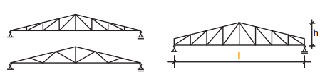
Fig. 12.21 Possible shapes.#
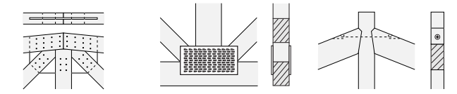
Fig. 12.22 Details (left: connection of upper chord, diagonals and vertical with coupler plate; middle: connection of bottom chord, diagonals and vertical with toothed plate; right: connection of upper chord and vertical with carpentry joint).#
The upper chords need lateral support.
Under stressed beam#
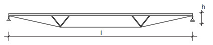
Fig. 12.23 Under stressed beam.#
Rules of thumb
Glulam beam
\(l = 8 - 80 m\)
\(h = \frac{l}{15} - \frac{l}{20}\)

Fig. 12.24 Possible shapes.#
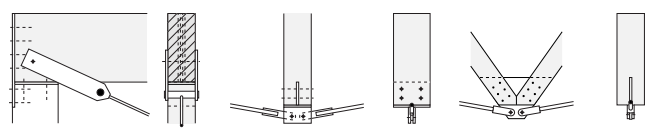
Fig. 12.25 Details (left: connection of the tensile bar at the support; middle: connection of the tensile bars and compressive strut with welded plates; right: connection of the tensile bars and diagonals with dowels).#
The upper edges need lateral support. The tensile bars also need lateral support to prevent twisting out of plane.
Rigid frame#
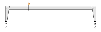
Fig. 12.26 Rigid frame.#
Rules of thumb
Glulam beam
\(l = 10 - 40 m\)
\(s = 4 - 8 m\)
\(h = \frac{l}{15} - \frac{l}{20}\)
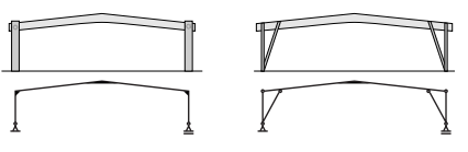
Fig. 12.27 Possible shapes.#
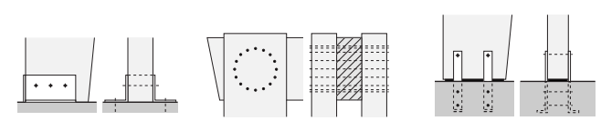
Fig. 12.28 Details (left: column-floor support with angle profiles and welded endplate (bolted); middle: moment resisting joint between double column and beam (dowels); right: column-floor support with cast-in plates (bolted)).#
This floor support connection is only suitable for low horizontal forces.
Three hinged frame (straight legs)#

Fig. 12.29 Three hinged frame (straight legs).#
Rules of thumb
Glulam beams, no tensile bar
\(l = 10 - 50 m\)
\(f = \frac{l}{3}\)
\(s = 5 - 8 m\)
\(h = \frac{l}{30} - \frac{l}{50}\)
Glulam beams, with tensile bar
\(l = 15 - 50 m\)
\(f = \frac{l}{6}\)
\(s = 5 - 8 m\)
\(h = \frac{l}{30} - \frac{l}{50}\)
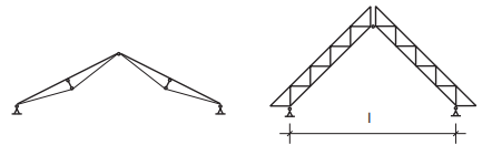
Fig. 12.30 Possible shapes.#
Note
\(l = 15 - 50 m\)
\(s = 5 - 8 m\)
\(h = \frac{l}{15} - \frac{l}{25}\)
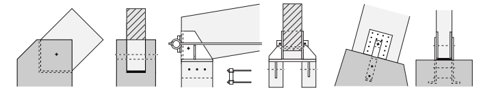
Fig. 12.31 Details (left: simple support, concrete footing with elastomeric bearing; middle: connection of double tensile bar to double column; right: column support on concrete footing with cast in plates (screwed)).#
This floor support connection is only suitable for low horizontal forces.
Three hinged frame (curved/kinked legs)#
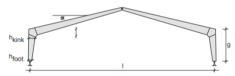
Fig. 12.32 Three hinged frame (curved/kinked legs).#
Rules of thumb
Frame with kinked corners
\(l = 15 - 50 m\)
\(\alpha = 20 ^{\circ}\)
\(s = 4 - 5 m \rightarrow h_{kink} = \frac{l + g}{28} and h_{foot} = 0.4 \cdot h_{kink}\)
\(s = 5 - 9 m \rightarrow h_{kink} = \frac{l + g}{24} and h_{foot} = 0.4 \cdot h_{kink}\)
Frame with bent corners
\(l = 15 - 50 m\)
\(r = 3.5 - 5 m\)
\(\alpha = 20 ^{\circ}\)
\(s = 4 - 5 m \rightarrow h_{kink} = \frac{l + g}{31} and h_{ridge} = 0.5 \cdot h_{kink} and h_{foot} = 0.67 \cdot h_{kink}\)
\(s = 5 - 9 m \rightarrow h_{kink} = \frac{l + g}{26} and h_{ridge} = 0.5 \cdot h_{kink} and h_{foot} = 0.67 \cdot h_{kink}\)
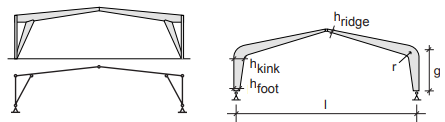
Fig. 12.33 Possible shapes.#
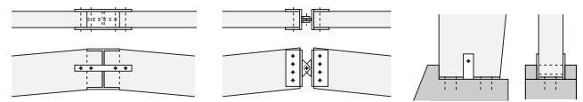
Fig. 12.34 Details (left: ridge connection with tensile connection and moulded I-profile; middle: ridge connection (bolted); right: support on concrete footing with welded steel plate).#
This floor support connection is only suitable for low horizontal forces.
Arch (solid and truss beam)#
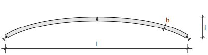
Fig. 12.35 Arch (solid and truss beam).#
Rules of thumb
Glulam beam
\(l = 20 - 100 m\)
\(f = \frac{l}{5} - \frac{l}{7}\)
\(s = \leq 5 m \rightarrow h = \frac{l}{45}\)
\(s = 5 - 9 m \rightarrow h = \frac{l}{40}\)
Glulam truss
\(l = 50 - 120 m\)
\(f = \frac{l}{5} - \frac{l}{8}\)
\(s = 5 - 10 m\)
\(h = \frac{l}{20} - \frac{l}{40}\)
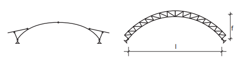
Fig. 12.36 Possible shapes.#
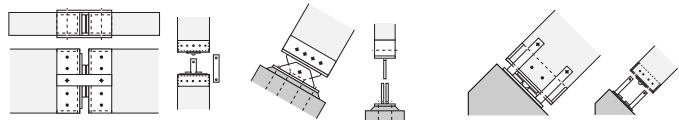
Fig. 12.37 Details (left: ridge connection with steel connectors (dowel); middle: support of arch (welded steel hinge); right: arch support).#