
8.10. Hollow sections and trusses#
Trusses#
The most economical application of a truss using rectangular or circular hollow sections demands the number of nodes to be as small as possible. For this reason the Warren truss is prefered most of the time. If no diagonals can or may be applied, this can for example be a wish of the architect, vierendeel-beams need to be applied, where chords and verticals are connected with moment resisting joints.
The truss bars are defined by their system length (ls) and the height (h) of the structure.
In general h=1/15 · l is an economical structural height.
Depending on the type of truss that is chosen the connections are of the X, T, Y, N or K-type. It is vital that the design of the connections is incorporated in the design as soon as possible. If the design of the bars is only based on the axial force, a lot of extra stiffeners may be needed in the connections. This does not mean that each connection needs to be designed in detail in the concept phase of a project, but the diagonals and chords need to be dimensioned such that a suitable node is possible which can be fabricated economically.
Guidelines for an optimal design:
Truss design is based on hinged connections between the elements. Secondary bending moments are neglected in the ‘static’ design.
In practice all nodes are designed centrically. This means the centerlines of all connecting elements intersect at one point. However, sometimes small eccentricities are unavoidable to aid simple fabrication.
Preferably the diagonals are connected with a small gap. If the two diagonals overlap at the connection, difficult cuts have to be made, especially with circular hollow sections. Welding is also more complicated at overlap joints. However, overlap joints have higher design resistances.
For trusses in general the following distribution is made: 50% of the weight for the compression chord; 30% of the weight for the tension chord; 20% for the diagonals.
Truss types#
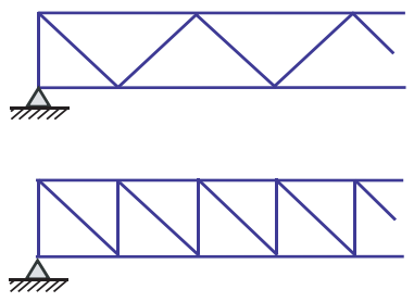
Fig. 8.46 Warren Truss and Pratt truss#
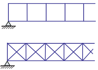
Fig. 8.47 Vierendeelbeam with and without bracings#
All trusses must be supported out of their plane to prevent them from ‘toppling over’. Also the chord under compression must be supported to prevent buckling out of plane.
Applications#
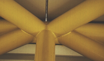
Fig. 8.48 Node RHS#
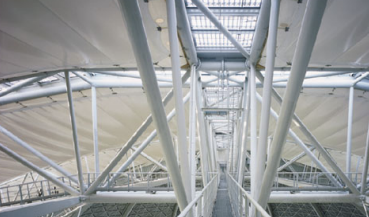
Fig. 8.49 Airshiphall in Germany#
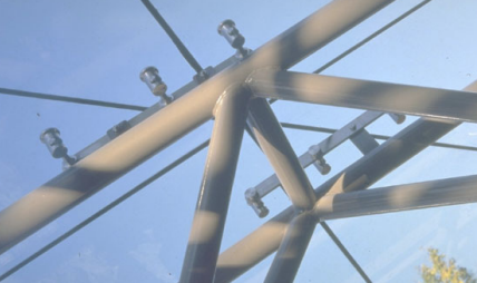
Fig. 8.50 Project Norway#
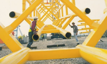
Fig. 8.51 Millenium Dome, London#
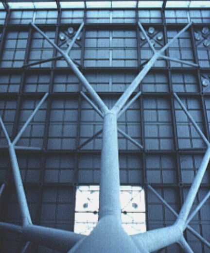
Fig. 8.52 Airport Stuttgart#
Truss connections#
Circular hollow sections can be connected by:
Prefabricated nodes.
Parts that allow for a bolted joint.
Welded to a node plate.
Directly welded to the other member.
For transportation or temporary connections during erection bolted joints are preferred. For space frames, a prefabricated node is preferred. The simplest solution is directly welding two member to each other. Today the required cutting for such a direct connection is no longer a problem.
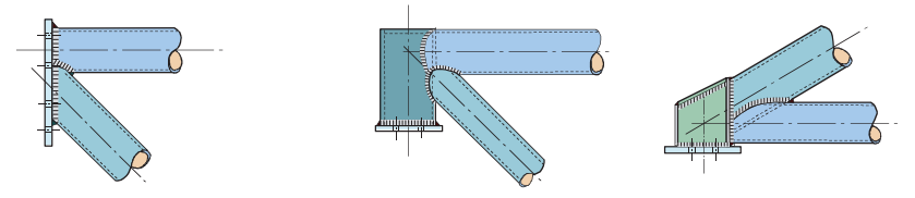
Fig. 8.53 CHS support#
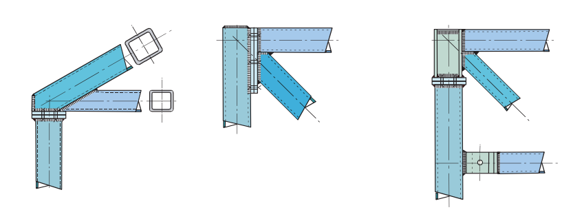
Fig. 8.54 RHS support#
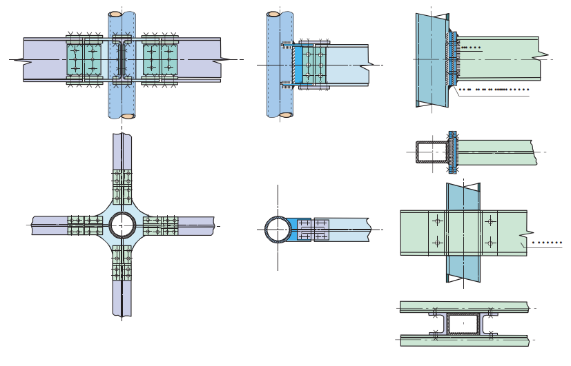
Fig. 8.55 Beam-column#
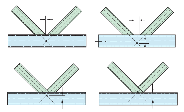
Fig. 8.56 Welds (K-joint)#
Connections, in this case a K-joint in a truss can be realized without overlap (a ‘gap’ joint) and with overlap. While designing such a joint, the possible effects of the geometry must be taken into account: eccentricity, peak stresses and possible fabrication problems.
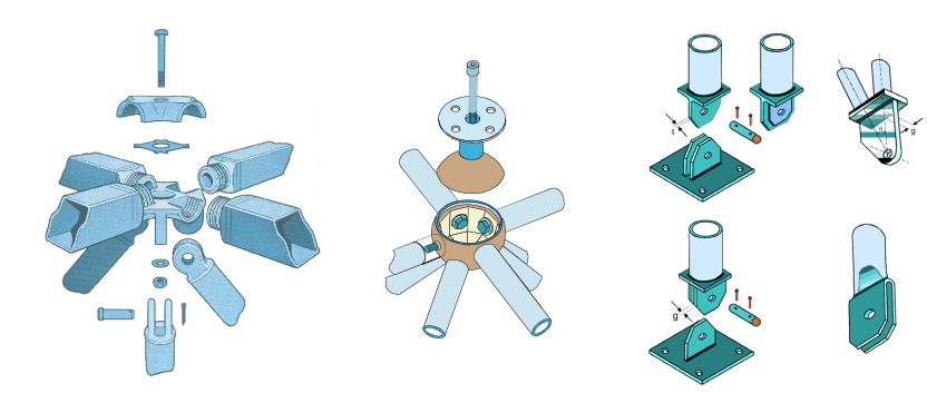
Fig. 8.57 Other#