
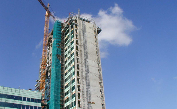
10.4. Composite floors#
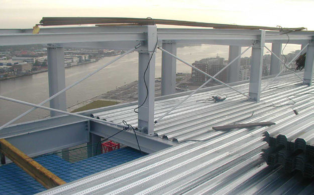
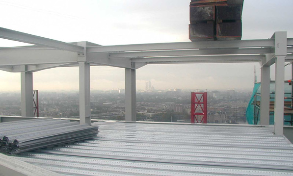
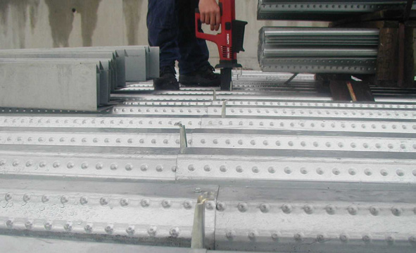
Corrugated sheet metal sheets are very suitable to act as formwork for cast in situ concrete floors. The sheets are light, are easily applied and can immediatly act as a working floor. The trapezoidal shape causes weight saving in comparison with a massive concrete floor.
Strengths of composite floors are the flexibility, construction speed, low mass, adaptability and high amoun of thermal mass with respect to the actual mass. The low self weight of the composite floor construction, \(210 - 340 kg/m^2\), causes the air and sound insulation to be lower than with prefab concrete elements. This problem can be solved with a suspended ceiling and/or a double floor. With these solutions the same results can be achieved as with a massive floor of 800 kg/m2.
The composite floors do not have a flat surface, but this does not have to be a problem if the correct connections are used. Floors with voids or curved façades can easily be built. The construction speed does not depend on the formwork system or hardening time. The laid out sheets act as working floor, formwork and a roof for the crews installing the building finishes.
Note
www.dutchengineering.nl The information on composite floors was written in cooperation with Hody B.V.
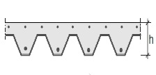
Fig. 10.8 Composite floor cross-section.#
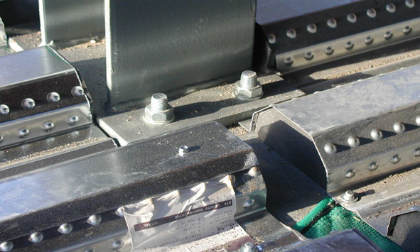
Fig. 10.9 Example of composite floor#
Applications#
Execution aspects#
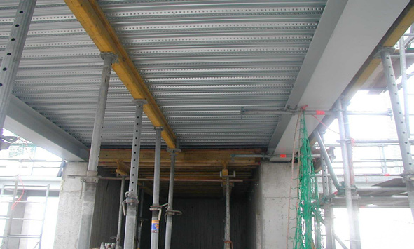
Corrugated, galvanized steel sheets with a thickness of 0,7 to 1,2 mm act as lost formwork and reinforcement for the composite floor. In principle the steel plates act as the main reinforcement. The extra reinforcement shown in the pictures prevents excessive cracking and has a beneficial effect of the behaviour of the flour under fire conditions. As a rule of thumb the thickness of the floor can be estimated as 1/30 of the span. Depending on the thickness of the floor, free spans up to 3,25 m are possible. If temporary supports are used the spans can increase up to 9,60 m. Whether the concrete floor is connected with shear connectors (studs) to the steel support beams or not determines the force distribution. If the shear studs are applied, the steel beam acts as tensile chord and the concrete will take up all the compression. A composite beam is formed. If no shear studs are applied, the beam and floor act separately. If the shear studs are highly loaded it is recommended to weld them directly to the beam, instead of welding them to the beam through the steel plates. Composite floors can also be applied in combination with integrated beams, where the corrugated sheet is placed on the widened bottom flange of a profile. Voids in the floor are provided with formwork to contain the wet concrete.
Product specifications HODY SB60 floor#
Fig. 10.10 HODY SB60 composite floor cross-section.#
Fig. 10.11 HODY SB60 composite floor example.#
Plate Reinforcement |
|
|---|---|
Plate thickness (including zinc) |
0.75 \([mm]\) / 0.88 \([mm]\) / 1.00 \([mm]\) |
Nets |
FeB 500 HKN |
Additional bars |
FeB 500 HKN / HWL |
Profile height |
60 \([mm]\) |
Concrete Total width |
1086 \([mm]\) |
Effective width |
1010 \([mm]\) |
Length |
Any length possible |
Material properties |
|
|---|---|
Characteristic yield stress |
Minimal 320 \([N/mm^2]\) |
Ultimate strain |
Minimal 17% |
Note
Based on: C28/35. Other strength classes can be applied except for lightweight concrete.
Spans#
Offices and lodging#
Span \([mm]\) |
Number of Props |
Thickness \([mm]\) |
Type of Top Reinforcement (for Continuous Floors) |
|---|---|---|---|
1.500 |
0 |
110 |
Reinforcement Net: 7-150 |
2.000 |
0 |
110 |
Reinforcement Net: 7-150 |
2.500 |
1 |
110 |
Reinforcement Net: 7-150 |
3.000 |
1 |
130 |
Reinforcement Net: 7-150 |
3.500 |
2 |
150 |
Reinforcement Net: 7-150 |
4.000 |
2 |
170 |
Reinforcement Net: 7-150 |
4.500 |
2 |
200 |
Reinforcement Net: 8-150 |
5.000 |
3 |
210 |
Reinforcement Net: 8-150 + 8 - 300 |
5.500 |
3 |
220 |
Reinforcement Net: 8-150 + 8 - 300 |
6.000 |
4 |
230 |
Reinforcement Net: 8-150 + 8 - 300 |
6.500 |
5 |
290 |
Reinforcement Net: 8-150 + 8 - 150 |
Note
Span table HODY SB60 floor OFFICES and LODGING SHEET THICKNESS 0,75 mm
strength class C20/25
topping max. 50 mm
no voids / ducts through the floor.
variable load 2,5 kN/m2
light walls 0,5 kN/m2
fire resistance: 30 minutes
minimal bearing length of steel plate: 50 mm on steel or concrete and 75 mm on other materials
minimal bearing length for casting is an extra 25 mm.
Residential#
Span \([mm]\) |
Number of Props |
Thickness \([mm]\) |
Type of Top Reinforcement (for Continuous Floors) |
|---|---|---|---|
1.500 |
0 |
110 |
Reinforcement Net: 7-150 |
2.000 |
0 |
110 |
Reinforcement Net: 7-150 |
2.500 |
1 |
110 |
Reinforcement Net: 7-150 |
3.000 |
1 |
130 |
Reinforcement Net: 7-150 |
3.500 |
2 |
150 |
Reinforcement Net: 7-150 |
4.000 |
2 |
170 |
Reinforcement Net: 7-150 |
4.500 |
2 |
200 |
Reinforcement Net: 8-150 |
5.000 |
3 |
210 |
Reinforcement Net: 8-150 + 8 - 300 |
5.500 |
3 |
220 |
Reinforcement Net: 8-150 + 8 - 300 |
6.000 |
4 |
230 |
Reinforcement Net: 8-150 + 8 - 300 |
6.500 |
5 |
290 |
Reinforcement Net: 8-150 + 8 - 150 |
Note
Span table HODY SB60 floor RESIDENTIAL BUILDINGS SHEET THICKNESS 0,75 mm
strength class C20/25
topping max. 50 mm
no voids / ducts through the floor
variable load 1,8 kN/m2
fire resistance 30 minutes
minimal bearing length of steel plate: 50 mm on steel or concrete and 75 mm on other materials
minimal bearing length for casting is an extra 25 mm.