
17.3. Global dimensioning cantilever beam#
Note
The calculations serve as examples for educational purposes and not as guidance for practice.
A cantilevered beam has at least one end unsupported. The relevant support point is moved slightly towards the center of the beam. Cantilevered beams are used, for example, in building overhangs, galleries, balconies, and canopies.
Cantilevered beams can be dimensioned using an estimation rule and then tested against the standard. For the section between the support points, the same rules apply as for a normal beam on two supports. For steel, the estimation rule is: \(h_{beam} = \frac{1}{20} \cdot l_{ov}\), where \(l_{ov}\) is the length of the beam section between the support points.
For the cantilever section (also for steel), the estimation rule is: \(h_{beam} = \frac{1}{20} \cdot 2 \cdot l_{out}\).
The support point at the cantilever must be able to transmit the moment to the section behind it. Therefore, the cross-section should be the same on both sides of the support point. The beam height is determined by the largest height found using the estimation rules.
The most favorable situation arises when the cantilever length is one-third of the distance between the two support points: \(l_{out} = \frac{1}{3} \cdot l_{ov}\).
The cantilevered beam must then be checked for strength and stiffness. To do this, we collect the beam data and determine the load on the beam.
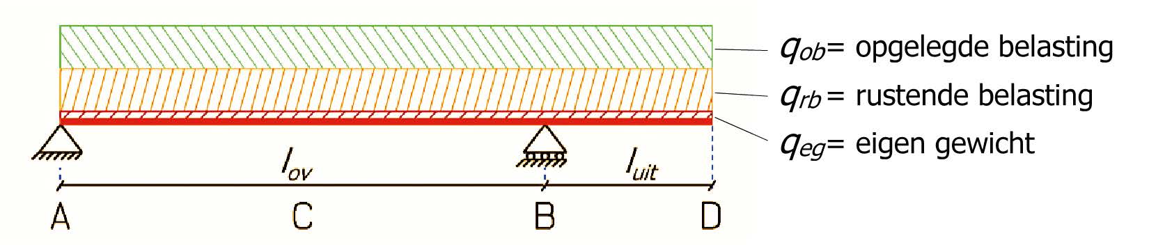
The load on the beam consists of three parts:
\(q_{eg}\): the self-weight of the beam.
\(q_{rb}\): the resting load on the beam, e.g., weight of floor construction, ceiling, hanging installations, floor finishes, etc.
\(q_{ob}\): the imposed load on the beam, in the form of variable load: \(q_Q\).
\(q_{eg}\) and \(q_{rb}\) together form the permanent load: \(q_G\).
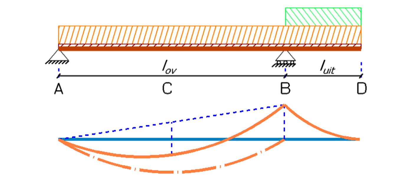
Regarding bending stress, there are two extremes in a cantilevered beam: the field moment at C between the supports and the support moment at the cantilever. To calculate these extremes, we need to divide the beam into two parts:
A regular beam on two supports (A-B).
The cantilevered part (B-D) that is considered to be clamped at the support.
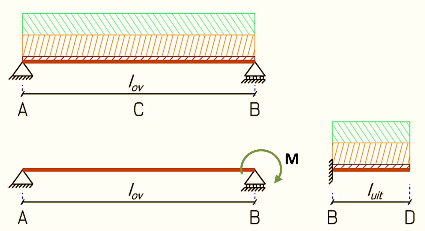
This results in three loading cases. The cantilevered part does not have a true fixed support but what is called a flexible support. The load on the cantilevered part creates a moment at support B. This moment will cause the beam section A-B to deflect upwards. As a result, the beam section B-D undergoes an angular rotation. Therefore, the beam section A-B is subjected not only to the load on this beam section but also to a moment due to the load on the cantilever.
By splitting the beam in this way, it is possible to use formulas from the formula sheet to calculate the stresses and deformations.
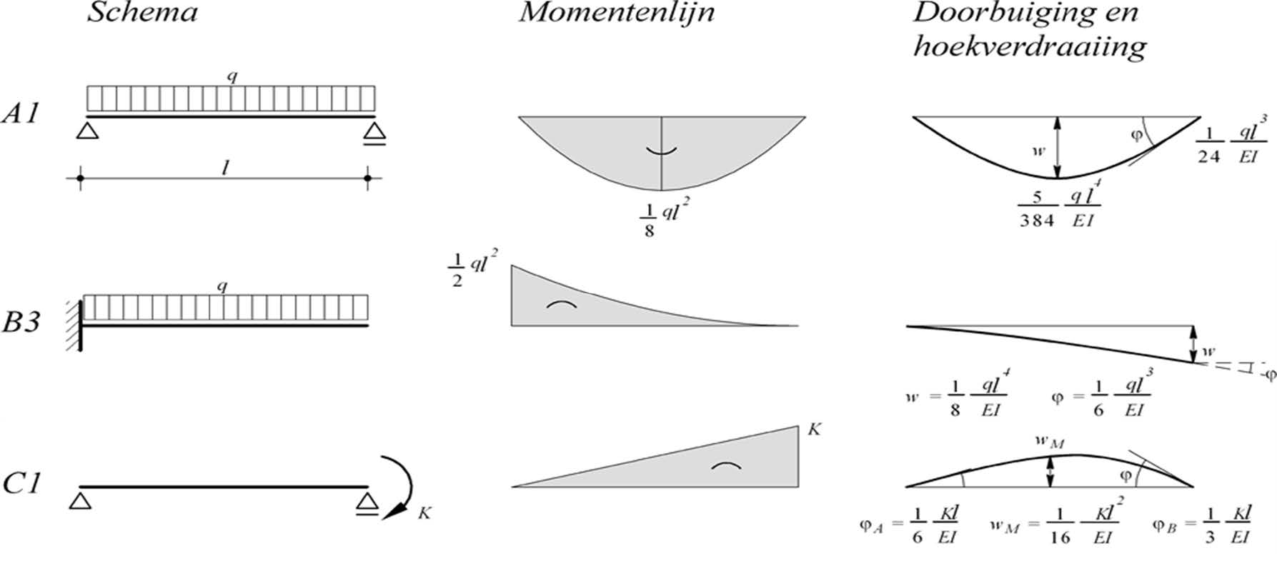
For the calculations, we need the following formulas for force effects (with the corresponding number on the formula sheet in brackets):
Formula Number |
|||
|---|---|---|---|
[A1] |
\(M_{veld}=\frac{1}{8} \cdot q_d l^2_{ov}\) |
\(w_{veld}= \frac{5}{384} \cdot \dfrac{q l^4_{ov}}{EI}\) |
\(\varphi=\frac{1}{24}\cdot \dfrac{q l^4_{ov}}{EI}\) |
[B3] |
\(M_{st.punt}=\frac{1}{2} \cdot q_d l_{uit}^2\) |
\(w_{uit 1}=\frac{1}{8} \cdot \dfrac{q l^4_{ov}}{EI}\) |
|
[C1] |
\(\varphi=\frac{1}{3} \cdot \dfrac{Kl_{ov}}{EI}\) |
\(K=\frac{1}{2} \cdot ql_{uit}^2\) |
\(w_{uit 2}=l_{uit} \cdot \varphi\) |
The load on beam section A-B will cause the cantilever to move upwards. The rise of endpoint D is given by:
Using [A1]:
This upward deflection is generally smaller than the deflection due to the variable load on the cantilever. Note that for the q-load in these formulas, different values for both \(q_{UGT}\) and \(q_{BGT}\) generally need to be used.
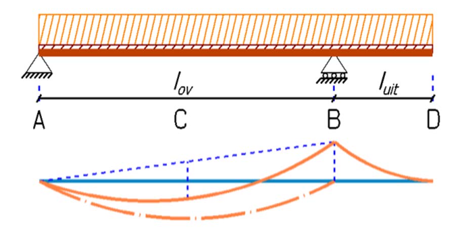
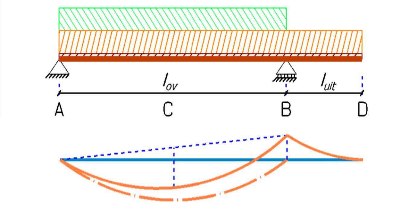
When examining the moment diagram for a distributed load \(q\) on the beam, we see that the size of the support moment is entirely determined by the load on the cantilever. The moment diagram of beam section A-B is effectively pulled up at B from 0 to the value of the support moment due to the load on the cantilever.
Without the cantilever, the moment at C in the middle of beam section A-B would be: \(M=\frac{1}{8}\cdot q l_{ov}^2\). For a beam cantilevered on one side, half of the support moment must be subtracted from this moment at C. In this cantilevered beam, the maximum field moment will not be at the middle C of the span A-B but slightly closer to the support point without the cantilever (A). For design calculations, the moment and deflection at the middle point C are sufficient.
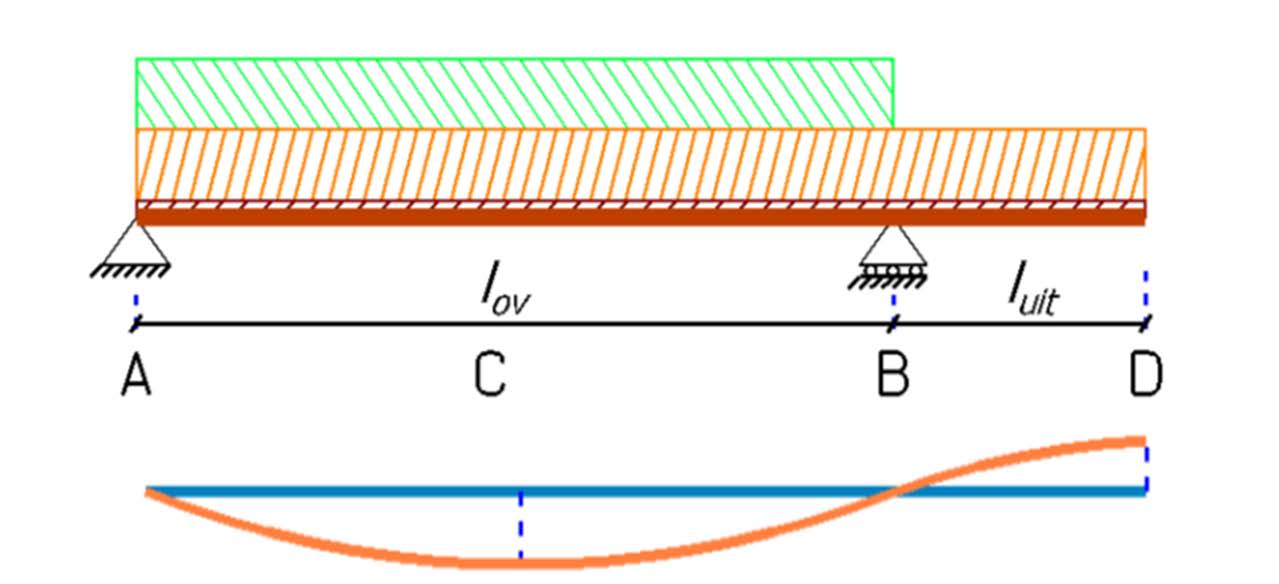
The load on the section between the supports and the load on the cantilever have opposite effects on the force distribution and deformation of the beam. Therefore, in the calculations, it must be assessed whether a load is favorable or unfavorable for the stress or deformation of the considered section. The load combination used should be chosen to be as unfavorable as possible to find the extremes. To determine these extremes, we distinguish between two load combinations:
Extreme load only on beam section A-B (between the supports) and reduced load on the cantilever B-D.
Extreme load only on the cantilever B-D and reduced load on beam section A-B.
As with a beam on two supports, we also only consider the Eurocode requirement for additional deflection here.
\(w_{bij,norm, uit} = 0.003 \cdot 2 l_{uit}\): Ordinary requirement for the additional deflection of a cantilever.
\(w_{bij,norm, uit}=0.002 \cdot 2 l_{uit}\): When the beam supports a wall.
\(w_{bij,norm, uit}=0.004 \cdot 2 l_{uit}\): When it is a roof (not a terrace).
Calculation of one-sided cantilevered steel beam#
An example is provided to illustrate the dimensioning and checking of a cantilevered beam. The starting point is again the office building used for the calculation of a beam on two supports. The third floor of this building projects outward, supported by cantilevered beams.
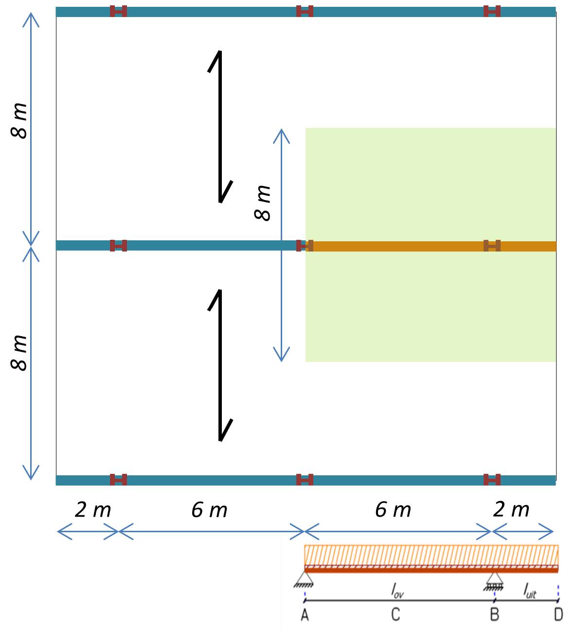
Below is the schematic floor plan of the third floor with the floor area supported by the cantilevered beam. \(l_{ov}=6\) meters and \(l_{uit} = 2\) meters. The distance between the beams is 8 meters. This is also the length of the channel plates.
Note
We assume a steel frame. For the beam profile, we use both estimation rules.
\(h_{ligger}=\frac{1}{20} \cdot l_{ov}=\frac{1}{20} \cdot 6000 [mm] = 300 [mm]\)
\(h_{ligger}=\frac{1}{20} \cdot 2 \cdot l_{uit}=\frac{1}{20} \cdot 2 \cdot 2000\ mm = 200\ mm\)
We choose a profile based on the largest of the found sizes: an HE320A profile. We can look up the profile data in the Steel Profiles App:
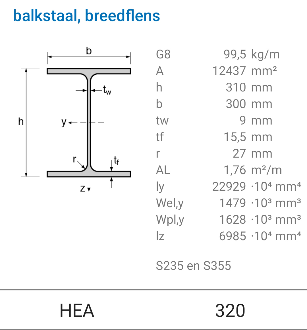
Fig. 17.4 The resting load consists of the weight of the channel plates, the finishing layer, and the ceiling with pipes. The required channel plate has a thickness of 200 mm and a weight of \(3.1 [kN/m^2]\). The 50 mm thick topping layer weighs \(1.2 [kN/m^2]\), and for the ceiling and pipes, \(0.6 [kN/m^2]\) is considered. Together, this gives a resting load of:#
\(3.1 [kN/m^2] + 1.2 [kN/m^2] + 0.6 [kN/m^2] = 4.9 [kN/m^2]\)
The distributed load on the beam for the resting load is therefore:
\(8 [m] \times 4.9 [kN/m^2] = 39.2 [kN/m]\)
This floor is also used as an office with lightweight partition walls, resulting in an imposed load of \(3 [kN/m^2]\). This gives a variable load on the beam of:
\(8 [m] \times 3 [kN/m^2] = 24 [kN/m]\)
The total permanent load becomes:
\(0.98 [kN/m] + 39.2 [kN/m] = 40.2 [kN/m]\)
With this data, we will check the beam for strength and stiffness. First, we consider the beam section between the supports and then the cantilever. In both calculations, the permanent load is present everywhere. However, different partial factors apply, depending on whether the load is favorable or unfavorable.
The variable load is only present for the calculation on the part where we determine the extremes.
Load Combination 1: Extreme Load on Beam Section A-B In this load combination, the section between the supports is loaded with a variable load of 24 kN/m. The permanent load of 40.2 kN/m is present on the entire beam.
To calculate the maximum occurring stress, we need to use the partial factors for the load. We look for the largest moment that can occur. In this case, it is the field moment at C. Load on the cantilever reduces the field moment. This load therefore has a favorable effect and should be taken as small as possible.
In the Eurocode, partial factors are established for this purpose. For safety class 2, the factors are:
Partial factors for Ultimate Limit State of Cantilevered Beam (Safety Class 2) Load Case 1: Variable load only on beam section A-B
For beam section A-B |
Unfavorable |
For cantilever B-D |
Favorable |
|---|---|---|---|
Partial factor \(\gamma_G\) for \(G_{field}\) |
1.2 |
\(\gamma_G\) for \(G_{cant}\) |
0.9 |
Partial factor \(\gamma_Q\) for \(Q_{field}\) |
1.5 |
\(\gamma_Q\) for \(Q_{cant}\) |
0 |
Note
The field moment due to the extreme load:
\(M_{veld;d}=\frac{1}{8}\cdot(\gamma_G\cdot q_G+\gamma_Q \cdot q_Q) \cdot l_{ov}^2 = \frac{1}{8} \cdot(1.2 \cdot40.2 [kN/m]+1.5 \cdot24 [kN/m])\cdot(6 [m])^2=379.1 [kNm]\)
Support moment due to reduced load:
\(M_{st.punt;d}=\frac{1}{2}\cdot \gamma_G \cdot q_{bb} \cdot l_{uit}^2 = \frac{1}{2}\cdot 0.9 \cdot 40.2 [kN/m] \cdot (2 [m])^2=72.4 [kNm]\)
The total field moment becomes:
\(M_{veld, max;d}=M_{veld;d}-\frac{1}{2}\cdot M_{st.punt;d}= 379.1 [kNm] -\frac{1}{2} \cdot 72.4 [kNm] =342.9 [kNm]\)
The stress in the beam due to the field moment at C:
\(\sigma_{m;d}= \dfrac{M_{veld, max;d}}{W_y} = \dfrac{342.9 \cdot10^6 [Nmm]}{1479 \cdot10^3 [mm^3]} =231.8 [N/mm^2]\)
With strength class S235, the Utilization Coefficient (U.C.):
\(U.C. \Rightarrow \dfrac{\sigma_{m,d}}{f_{m,d}} = \dfrac{231.8 [N/mm^2]}{235 [N/mm^2]} =0.99 \leq 1.0 \Rightarrow \textcolor{green}{\text{Satisfied}}\)
During the calculation of the maximum additional deflection of beam section A-B, the variable load should be placed on this beam section. Deformation is not a safety check, so the partial factors can be omitted, i.e., equal to 1 (and 0 for favorable variable loads).
Note
Since steel does not experience creep, the additional deflection depends only on the variable load present.
The deflection at the midpoint of A-B due to the load on A-B is:
\(w_{bij, veld}= \frac{5}{384} \cdot \dfrac{(q_Q)\cdot l_{ov}^4}{EI_y} = \frac{5}{384} \cdot \dfrac{24 [N/mm] \cdot(6000 [mm])^4}{210000 [N/mm^2] \cdot 229.3 \cdot 10^6 [mm^4] } = 8.4 [mm]\)
For the deflection requirement, we use the stringent requirement due to the potential placement of lightweight partition walls:
\(w_{bij, norm}=0.002 \cdot l_{ov}= 0.002 \cdot 6000 [mm]=12 [mm]\)
This gives:
\(U.C. \Rightarrow \dfrac{w_{bij, veld}}{w_{bij, norm}} = \dfrac{8.4 [mm]}{12 [mm]} = 0.7 < 1.0 \Rightarrow \textcolor{green}{\text{Satisfied}}\)
Load Combination 2: Extreme Load on Cantilever B–D.
In this load combination, only the cantilever carries variable load. The permanent load applies to the entire beam.
The support moment at B is solely determined by the load on the cantilever, not the load on beam section A-B. The maximum moment occurs when the cantilever is extremely loaded, by both the permanent and variable loads. Here too, we can determine the partial factors, where those for beam section A-B are not applicable.
Partial factors for Ultimate Limit State of Cantilevered Beam (Safety Class 2) Load Case 1: Variable load only on beam section B-D
For beam section A-B |
Unfavorable |
For cantilever B-D |
Favorable |
|---|---|---|---|
Partial factor \(\gamma_G\) for \(G_{field}\) |
1.2 |
\(\gamma_G\) for \(G_{cant}\) |
0.9 |
Partial factor \(\gamma_Q\) for \(Q_{field}\) |
1.5 |
\(\gamma_Q\) for \(Q_{cant}\) |
0 |
Note
This load combination results in the largest moment above the support point (B):
\(M_{st.punt;max;d}=\frac{1}{2} \cdot (\gamma_G \cdot q_G+\gamma_Q \cdot q_Q) \cdot l_{uit}^2=\frac{1}{2} \cdot (1.2 \cdot 40.2 [kN/m]+1.5 \cdot 24 [kN/m]) \cdot (2 [m])^2=168.5 [kNm]\)
This results in a stress in the steel of:
\(\sigma_{m;d}= \dfrac{M_{st.punt; max; d}}{W_y} =\dfrac{168.5 \cdot 10^6 [Nmm]}{1479\cdot10^3 [mm^3]} =113.9 [N/mm^2]\)
For S235, the Utilization Coefficient (U.C.):
\(U.C. \Rightarrow \dfrac{\sigma_{m,d}}{f_{m,d}} = \dfrac{113.9 [N/mm^2]}{235 [N/mm^2] } =0.48≤ 1 \Rightarrow \) \textcolor{green}{Satisfied}
In this load combination, the deflection at the end of the cantilever needs to be determined. The maximum additional deflection at D occurs with only a variable load on the cantilever and not on beam section A-B.
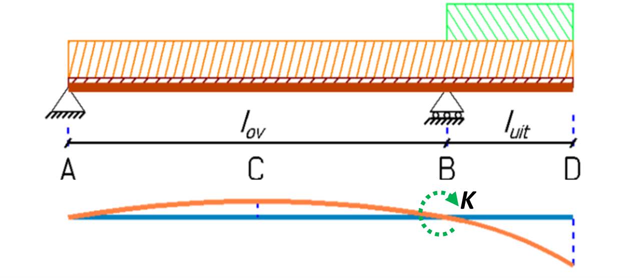
To calculate the deflection at D, we need to divide the beam into two parts: a clamped beam B-D with the variable load, and a beam on two supports A-B with a moment K at support B, caused by the load on the cantilever beam B-D.
Note
From the formula sheet, we use the formula for the deflection of a ‘clamped’ beam [B3] to determine the deflection of the cantilever:
\(w_{uit 1}=\frac{1}{8} \cdot \dfrac{q_Q\cdot l_{uit}^4}{EI_y}= \frac{1}{8} \cdot \dfrac{24 [N/mm] \cdot (2000 [mm])^4}{210000 [N/mm^2] \cdot 229,3 \cdot 10^6 [mm^4]} =1,0 [mm]\)
The moment at B causes a deflection of beam section A-B, leading to an angular rotation at B, causing beam section B-D to tilt downwards (see-saw effect). We can calculate the moment at B with [B]:
\(K=\frac{1}{2} \cdot q_Q \cdot l_{uit}^2 =\frac{1}{2}\cdot 24 [N/mm] \cdot (2000 [mm])^2=48 \cdot 10^6 [Nmm]\)
The angular rotation due to moment K can be calculated with [C1] (Note: here without partial factor!):
\(\varphi=\frac{1}{3} \cdot \dfrac{K\cdot l_{ov}}{EI} = \frac{1}{3} \cdot \dfrac{48 \cdot 10^6 [Nmm] \cdot 6000 [mm]}{210000 [N/mm^2] \cdot 229,3 \cdot 10^6 [mm^4]} =0,002 [rad]\)
Using the angular rotation, we can determine the deflection of the cantilever due to the see-saw effect:
\(w_{uit2}=l_{uit} \cdot \varphi = 2000 [mm] \cdot 0,002=4,0 [mm]\)
The total deflection due to bending and the see-saw effect is:
\(w_{bij,uit}=w_{uit 1}+w_{uit 2}=1,0 [mm]+4,0 [mm]=5,0 [mm]\)
For deflection, we use the strict requirement because walls can be placed on the beam. For a cantilever, we have:
\(w_{bij, norm, uit}=0,002 \cdot 2 \cdot l_{uit}= 2 \cdot 0,002 \cdot 2 \cdot 2000\ [mm]= 8 [mm]\)
With this, we can perform a U.C.:
\(U.C. \rightarrow \dfrac{w_{bij, uit}}{w_{bij, norm, uit}} = \dfrac{5 [mm]}{8 [mm]} =0,6 \leq 1,0 \ \Rightarrow \textcolor{green}{\text{Satisfied}}\)
Evaluation of Verification Calculations:
The selected beam meets both the strength and stiffness requirements for the beam section between the supports as well as for the cantilever.
The strength of the beam section between the supports proves to be critical for this beam. By using a higher strength class, S355, a slightly more slender profile can be used: HE300A. In that case, the deflection of the beam section between the supports becomes critical. A more slender profile (HE280A) is possible if there are no walls on the beam so that the normal deflection requirement applies: \(w_{bij, norm}=0.003 \cdot l_{uit}\).
For this beam, the support moment and the settlement at the end of the cantilever are not critical. This means that the cantilever can be made slightly longer. With an HE300A, the cantilever can be 0.2 metres longer: \(l_{uit}=2.2 [m]\). By using an HE320A, the cantilever can even be half a metre longer: \(l_{uit}=2.5 [m]\). The deflection of the cantilever then becomes critical.