
17.4. Global dimensioning truss beam#
Note
The calculations serve as examples for educational purposes and not as guidance for practice.
For larger spans, a simple beam will no longer suffice. A suitable element for consideration is a truss beam. In construction, the term “truss” is also used for timber frames with masonry infill, commonly seen in buildings in Germany. In this chapter, we refer to a truss as a structural element composed of triangles. Unlike a quadrilateral, a triangle is rigid. The simplest truss is a triangular truss, consisting of a single triangle.
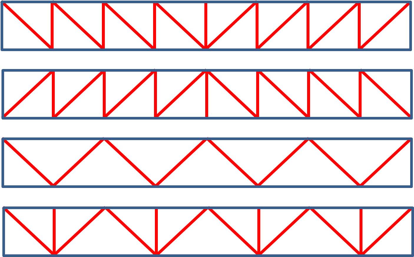
A truss beam is composed of multiple triangles side by side, forming a rigid whole. Truss beams distinguish between chord members (blue) and web members (red). Chord members include the top and bottom chords and usually vertical end posts. The web members consist of diagonals and often vertical posts. Two patterns are distinguished: N-trusses and V-trusses. In N-trusses, we further distinguish between trusses with descending and ascending diagonals. V-trusses may also include vertical posts.
The nodes of a truss are essentially hinged together. Consequently, no moments can be transferred through the nodes, and the load must be transmitted as axial force. Therefore, the stresses in the members of the truss are primarily tensile and compressive stresses. In beams, these are mostly bending stresses. Bending generally results in high stresses and deformations, whereas axial forces produce much lower stresses and deformations.
In a truss, the material is thus used more efficiently. A disadvantage of a truss is the relatively large construction height compared to a beam. As a rule of thumb for trusses under the roof, we use: \(h=\frac{1}{10}\) to \(\frac{1}{15}\) of the span.
The span is the distance between the supports. For floors, much more substantial trusses are needed. Therefore, storey-height trusses are usually used, so the construction height of the floor itself can remain relatively small. A drawback of these trusses is the diagonals, which can be considered intrusive. An alternative is the vierendeel truss. In vierendeel trusses, however, the members are subject to bending, requiring much more substantial profiles with rigid connections. This truss, therefore, demands much more material to meet strength and stiffness requirements.
When designing a truss, profiles or weights can be assigned using estimation rules. The simplest way is to estimate the weight of the truss. Based on the total load on the truss, the following roughly estimated weights can be used:
The required profiles can then be calculated using the formula:
\(f_{t;d}\) is the design value of the tensile strength. This is essentially equal to the design value of the compressive strength: \(f_{c;d}\). However, for members subjected to compression, buckling must also be considered. Additionally, if the top chord carries roof or floor plates, it must also be checked for bending. The total stress is then the sum of \(\sigma_{c;d}\) and \(\sigma_{m;d}\), which must be less than \(f_{c;d}\).
For bending of the top chord, it applies that \(\sigma_{t;d}+\sigma_{m;d} \leq f_{t;d}\). For the stresses in these verification calculations, we naturally use the absolute values.
For a truss where the bottom or top chord is subjected to a line load in bending, the size of the bottom or top chord can be estimated by considering the chord members between the nodes as beams on two supports. Then, use the estimation rules for a floor or roof beam.
Truss Loaded by a Single Point Load#
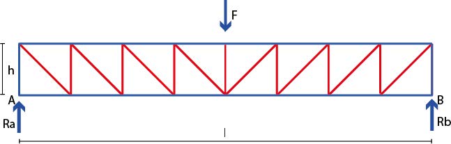
Here we consider an N-truss with descending diagonals, which results in tensile forces in the diagonals, allowing them to be relatively slender. Suppose the truss is loaded at the centre by a point load \(F\). The point load must be supported by the supports. The force is transmitted through the vertical and diagonal web members to the vertical end posts and then to both supports. At the supports, a vertical reaction force equal to \(\frac{1}{2}F\) occurs.
The vertical members, disregarding the self-weight, all bear the same load. Considering the vertical equilibrium at the supports, it is easy to see that the member force equals the support reaction force: \(F_{verticaal} = \frac{1}{2}F\).
The diagonals must also bear the same load. Considering the vertical equilibrium at the left upper joint, the vertical component of the diagonal member force equals \(\frac{1}{2}F\).
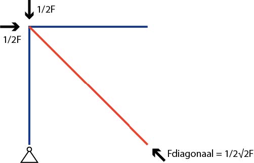
In this truss, the panels are square. Therefore, the diagonals run at a 45° angle. Using the Pythagorean theorem, it is easy to determine that the member force in the diagonal is equal to:
The top and bottom chord members are most heavily loaded in the middle. For designing the truss, these members are therefore the most relevant. Similar to a beam, the external moment due to the load on the truss must also be determined. For a truss on two supports with a point load in the middle, the following applies: \(M_{uitw} = \frac{1}{4} F\cdot l_{vw}\).
For equilibrium, the external moment must be equal to the internal moment: \(M_{uitw.} = M_{inw.}\). The internal moment here is equal to the couple of the forces in the top and bottom chords. These forces, due to equilibrium, are equal in magnitude but opposite in direction: compression in the top chord and tension in the bottom chord. Now, \(M_{inw.} = F_{staaf} \cdot h\), where \(h\) is the height of the truss. The member force then becomes:
It is evident that the larger the truss height, the smaller the forces in the top and bottom chords.
For a truss with multiple loads at the joints in the top chord, the same principle applies. Again, we can establish the external moment at the midpoint of the span by cutting the truss and summing up the moments. The reaction forces contribute a positive moment. The loads at the joints cause negative moments. Refer to subsequent sections for the detailed elaboration of this. For a truss to work optimally, the loads should act at the joints, not midway along a member.
Truss Loaded by Uniformly Distributed Load on the Top Chord#
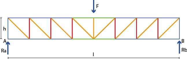
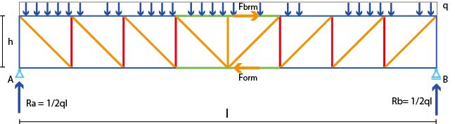
A truss beam supporting a concrete floor is often loaded by a uniformly distributed load. We can also calculate the reaction forces for this case. Each reaction force is, of course, equal to half of the total load (Figure \ref{fig:afb43}).
With a total load equal to \(q\cdot l_{vw}\), the reaction force \(R_A=\frac{1}{2}\cdot q\cdot l_{vw}\). This is also the magnitude of the compressive force in the end post and the vertical component of the tensile force in the diagonal in the end field of a truss with descending diagonals. For the maximum moment of a truss beam loaded by a uniformly distributed load, the following applies:
This is the external moment. The internal and external moments must be equal. The internal moment equals the member force times the truss height:
The member force in the end post at support A is equal to the reaction force of the support: \(\frac{1}{2}ql_{vw}\). For the diagonal force in the end field, we need to again consider the vertical equilibrium at the upper joint near A. Note that half of the distributed load q in the end field is directly transferred to the left upper joint and not through the diagonal. Therefore, the vertical component of the end diagonal is smaller than \(\frac{1}{2}ql_{vw}\). Refer to the subsequent sections for further elaboration.
Multi-Point Load on Storey-Height Truss Beams#
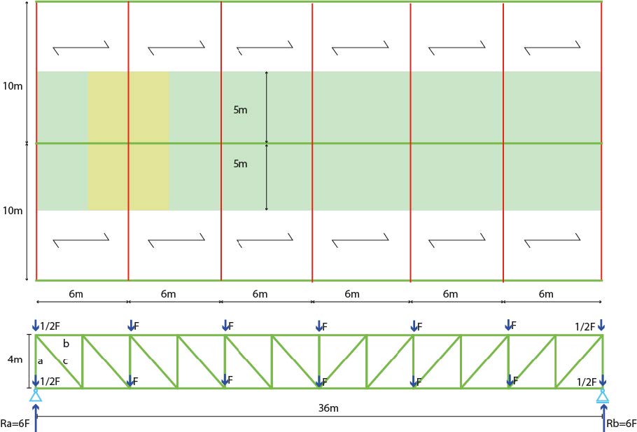
In a building with office functions on the 1st and 2nd floors, a large column-free space is desired on the ground floor. Therefore, storey-height truss beams are installed with a length of 36 meters and a height of 4 meters, simultaneously supporting the two floors. Some joints support a secondary floor beam. These secondary floor beams (HEA profiles) have a clear span of 10 meters. They support a steel plate concrete floor (floor thickness 225 mm) with a finishing layer, pipes, and a ceiling. The steel plates span 6 meters.
Note
The steel plate concrete floor has a total weight of \(3.6\ kN/m^2\). The finishing layer, pipes, and ceiling together weigh \(1.8 \ kN/m^2\). This makes the total floor weight \(5.4 [kN/m^2]\).
From the schematic load-bearing plan, it is apparent that an area of \(6 \cdot 5 [m^2]\) is supported on each side of the truss joint. So, the total area at a joint is:
\(6 \cdot (5 [m]+5 [m]) = 60\ m^2\) (yellow area).
This results in a load of:
\(60 [m^2] \cdot 5.4 [kN/m^2] = 324 [kN]\).
For the floor beams, we choose a HE500A with a mass of \(155 [kg/m]\), or a weight of \(0.01 \cdot 155 [kg/m] = 1.55 [kN/m]\). This gives a load of:
\((5 [m] + 5 [m]) \cdot 1.55 [kN/m] = 15.5 [kN]\).
Therefore, the total static load on the truss beam per loaded joint is:
\(324 [kN] + 15.5 [kN] = 339.5 [kN]\).
In addition to this, there’s the weight of the truss itself. If we estimate this weight to be \(10[%]\) of the static load, it becomes \(34 [kN]\). Thus, the total permanent load becomes (rounded off):
\(340 [kN] + 34 [kN] = 374 [kN]\).
For an office function, according to the National Annex to the Eurocode, the imposed load is \(2.5 \ kN/m^2\). With lightweight partition walls (usually estimated at \(0.5 \ kN/m^2\)), this becomes a load of \(3 \ kN/m^2\). As a point load on the truss, this load needs to be multiplied by the yellow area in Figure \ref{fig:afb44}:
\(\mathsf{6\ m \cdot (5\ m + 5\ m) \cdot 3\ kN/m = 180\ kN}\)
The design value for the ULS (ultimate limit state) becomes:
\(\mathsf{F_d = 1.2 \cdot 374\ kN + 1.5 \cdot 180\ kN = 718\ kN}\).
This force \(\mathsf{F_d}\) acts as a point load on the truss, both on the top and bottom chords. The reaction due to these joint loads for two floors then becomes:
\(\mathsf{2 \cdot (\frac{1}{2}F_d + F_d + F_d + \frac{1}{2} F_d) = 6 F_d \cdot R_A = 6 \cdot 718\ kN = 4309\ kN}\).