
14.2. Concrete and steel calculation exercise 2023-2024#
Note
The calculations serve as examples for educational purposes and not as guidance for practice.
This page provides an overview of Part 1 of the assignment for the course Concrete and Steel Structures (CTB2220-14) as published for students in the 2023-2024 academic year during the second quarter. The aim is to serve as an additional example, offering students greater insight into the portion of the course that focuses on safety. Various parameters in the assignment are dependent on the last three digits of the student number. These parameters are denoted as X, Y, and Z (1234XYZ). Since this assignment serves as an example, the parameters have been set to X = 0, Y = 0, and Z = 0 in this solution.
Note
To provide more coherence in the Quick Reference, the flowchart for structural design developed by Lisette Klompenhouwer, Bsc (2015) is provided in the margin to allow for oversight in where we are in the design process. The full flowchart can be found here: The design process.
Introduction
In a picturesque town on the outskirts of Amsterdam stands the home of Mr and Mrs Van Wijk. A charming family house with a concrete structure that has already gathered many memories. When their family expanded, they decided it was time for more space. The question that occupied their minds was how to add an extra floor without placing too much strain on the existing structure.
Mr Van Wijk approached our structural engineering firm for advice. Our colleague, Maria, came up with the brilliant idea of using a lightweight steel structure. She believed this would be the perfect solution to add an additional floor without requiring drastic alterations to the existing concrete structure and foundation. Her design was innovative and promised to provide the Van Wijk family with the space they needed, without having to completely renovate their home.
Unfortunately, Maria became involved in another urgent project and had to step away from this design. That’s when you, as her colleague, take up the challenge of bringing her vision to life. You delve deeper into Maria’s design and begin to work out the details.
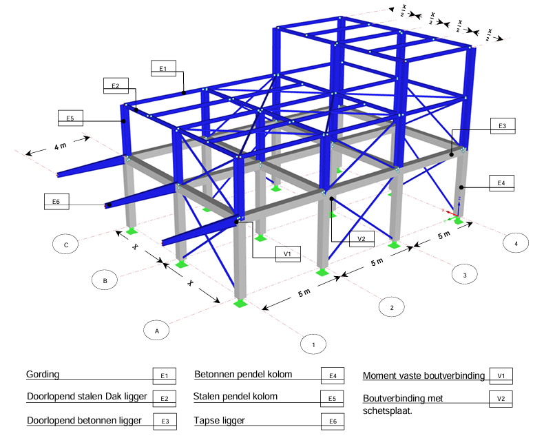
Fig. 14.2 3D-model including dimensions and annotations.#
It was a complex task to ensure that the new steel structure would seamlessly integrate with the existing concrete structure. Through careful calculations and thorough research, the new design began to take shape. Fig. 14.2 shows a 3D model, while Fig. 14.3 and Fig. 14.4 present the mechanical design drawings of the structure. Additional design drawings can be found in Appendix A - Design drawings.
As mentioned earlier, the ground floor of the family house consists of concrete, while the additional structure for the first and second floors is made of steel. The ground floor has a height of 4 metres, the first floor has a height of 3 metres, and the second floor has a height of 2.8 metres, as shown in Fig. 14.4. The centre-to-centre distance between the columns in the longitudinal direction is 5 metres, while the span in the transverse direction depends on your student number (X), as indicated in Table 14.1. For this example, X = 0, so the span is 3.5 m.
Studentnumber X |
Span [m] |
|---|---|
0 en 1 |
3,5 |
2 en 3 |
4,0 |
4 en 5 |
4,5 |
6 en 7 |
5 |
8 en 9 |
5,5 |
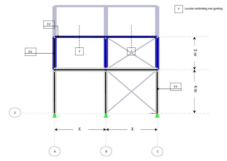
Fig. 14.3 Mechanical scheme in transverse direction.#
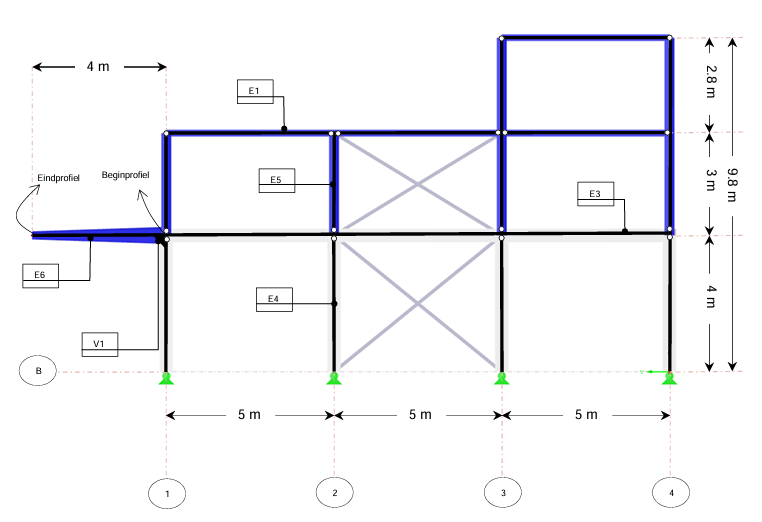
Fig. 14.4 Mechanical scheme in longitudinal direction.#
The concrete beams on axes A, B, and C are continuous beams, as are the steel roof beams on axes 1, 2, 3, and 4. The purlins span 5 metres and are hinged to the continuous steel roof beams. The spacing between the purlins depends on your student number. The steel and concrete profiles used in the structure are also based on your student number and can be found in questions 2 and 3, respectively.
At the rear of the house, three steel tapered beams have been designed to support the balcony (see Fig. 14.2). These cantilevered beams have a length of 4 metres. The profile dimensions at the start and end of these tapered beams are provided in question 2 and are marked in Fig. 14.4.
Hollow-core slabs are used for both the ground floor and the upper floors. These floors transfer loads in one specific direction, as shown in the drawing in Fig. 14.14 in Appendix A - Design drawings. The roof across the entire building is covered with steel roof panels (see Fig. 14.15 in Appendix A - Design drawings). Like the hollow-core slabs, the roof panels also transfer loads in one direction.
Safety and Loads#
The structure is designed based on the fundamental load combinations, considering both permanent and variable loads.
Permanent Loads#
The permanent load includes the self-weight of the main structure as well as the floor and roof elements. The self-weight of the steel roof elements and the hollow-core slabs can be found in Table 14.2.
Component |
Symbol |
Load \(kN/m^2\) |
|---|---|---|
Steel roof panel |
\(g_{k,self-weight,roof\_panel}\) |
0.12 |
Hollow-core slab |
\(g_{k,self-weight,hollow\_core}\) |
3.02 |
The dimensions of the steel purlin, steel beam, steel column, concrete beam, and concrete column can be found in {numref}profile_dimensions:
X |
Roof Span [m] |
Floor Span [m] |
Purlin |
Concrete Beam [m²] |
Concrete Column [m] |
|---|---|---|---|---|---|
0 and 1 |
1.75 |
3.5 |
IPE140 |
0.2 x 0.35 |
0.15 x 0.15 |
2 and 3 |
2 |
4 |
IPE160 |
0.22 x 0.35 |
0.175 x 0.175 |
4 and 5 |
2.25 |
4.5 |
IPE180 |
0.24 x 0.37 |
0.2 x 0.2 |
6 and 7 |
2.5 |
5 |
IPE180 |
0.24 x 0.38 |
0.225 x 0.225 |
8 and 9 |
2.75 |
5.5 |
IPE180 |
0.25 x 0.4 |
0.25 x 0.25 |
In addition to the self-weight of the structural elements, a permanent load of \(\mathbf{g_{k,permanent,roof} = 0.45 kN/m^2}\) has been applied to the steel roof. This load accounts for the ceiling, insulation material, roofing, and solar panels. An illustration is provided in {numref}figure4.
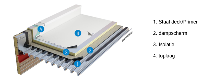
Fig. 14.5 Steel roof principal.#
Indoors, a permanent floor load of \(\mathbf{g_{k,permanent,floor} = 0.25 kN/m^2}\) is applied. This load accounts for the ceiling, floor finishes, and electrical wiring and piping. An illustration is provided in Fig. 14.6.
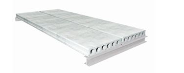
Fig. 14.6 Hollow core slab.#
The self-weight of the façade elements is considered negligible for this assignment.
Variable Loads#
For variable loads (loads that can “change” during the structure’s lifespan), the roof is subjected to imposed roof loads (maintenance activities), snow loads, and wind loads. For the indoor spaces, variable loads include those from “movable” partitions and general interior loads.
Imposed Roof Load#
An imposed roof load of \(\mathbf{g_{k,imposed,roof} = 1.0 kN/m^2}\) applies over a contiguous rectangular area of up to \(\mathbf{10 \ m^2}\). This area can be located anywhere on the roof surface, as illustrated in Fig. 14.7.
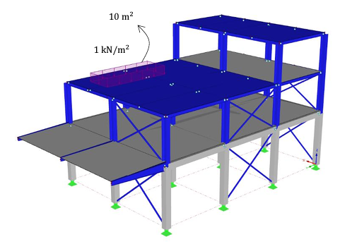
Fig. 14.7 Roof load.#
Snow Load#
The snow load is calculated as \(\mathbf{g_{k,snow} = 0.56 kN/m^2}\). Normally, due to the height difference along axis 3, an additional load for snow accumulation would also be considered. However, for this assignment, this has been disregarded.
Wind Load#
In this assignment, wind load is excluded, except for the upward wind acting on the cantilevered beam. Typically, wind has a significant influence on the design of elements such as roof beams and stability components. The characteristic wind load is shown in Fig. 14.8 and is calculated as \(\mathbf{g_{k,wind,upward,balcony} = 0.82 kN/m^2}\).
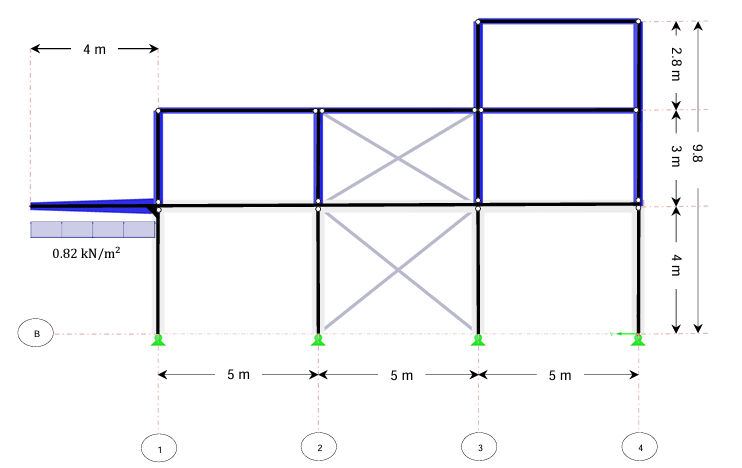
Fig. 14.8 Wind load.#
Indoor Spaces + Movable Partitions and Balcony Load#
Variable loads in indoor spaces account for loads from occupants, furniture, etc. A distinction is made between indoor loads and loads on the terrace.
The characteristic load value for floors is \(g_{k} = 1.75 kN/m^2\). However, because the space is large and the homeowners want the flexibility to rearrange and remodel the spaces, non-load-bearing walls have been chosen. These movable partitions can be placed anywhere on the floor. The lightest partition wall is considered and is accounted for as a uniformly distributed load of 0.5 kN/m². This brings the total (indoor) floor load to \(\mathbf{g_{k,imposed,floor} = 2.25 kN/m^2}\).
The load on the balcony, as per the Eurocode, is \(\mathbf{g_{k,imposed,balcony} = 2.5 kN/m^2}\).
Note
In alle calculations \(\mathbf{g = 10.0 \ m/s^2}\) is used!
Classification#
\(\mathbf{\text{Question a}}\)
Before determining the load combinations, the consequence class must be established. This depends on the intended use of the structure. Into which consequence class should this structure be categorised?
Answer
CC1
\(\mathbf{\text{Question b}}\)
Would there be a change in the consequence class if the owner had chosen to add 4 storeys?
(Hint: Refer to NEN-EN 1990:2019/NB:2019, as this is not included in the reader.)
Answer
CC2
\(\mathbf{\text{Question c}}\)
What load factors should be used for favourable and unfavourable permanent and variable loads?
Permanent favourable Permanent unfavourable Variable favourable Variable unfavourable BGT permanent BGT variable
Refer to Loads and limit states.
Answer
Permanent favourable: 0.9
Permanent unfavourable: 1.1 or 1.2
Variable favourable: 0
Variable unfavourable: 1.35
BGT permanent: 1
BGT variable: 1
Loads#
\(\mathbf{\text{Question d}}\)
Determine the following characteristic permanent loads in \([kN/m]\) acting on the structural elements. For steel profiles, you can use the “Staalprofielen” app from Bouwen met Staal or the website: https://www.bouwenmetstaal.nl/tools/staalprofielen. Refer to Appendix A - Design drawings for the centre-to-centre spans of the roofs.
\(G_{purlin,axis,B}\)
\(G_{cantilever,axis,B}\), also called the tapered beam, use the start profile for this calculation
\(G_{steel,column,axis,B2}\)
\(G_{roof,beam,axis,2}\)
\(G_{concrete,beam,axis,B}\)
\(G_{concrete,column,axis,B2}\)
\(G_{roof,axis,B}\)
\(G_{floor,axis,B}\)
Student Number X |
Tapered Beam Start Profile |
Steel Beam |
Steel Column |
|---|---|---|---|
0 or 1 |
IPE400 |
IPE120 |
HEA120 |
2 or 3 |
IPE450 |
IPE140 |
HEA140 |
4 or 5 |
IPE450 |
IPE160 |
HEA160 |
6 or 7 |
IPE500 |
IPE180 |
HEA180 |
8 or 9 |
IPE500 |
IPE200 |
HEA200 |
Answer
From Table 14.3 it follows that the purlin for X=0 consists of IPE140, this steel profile gives \(G = 12.9 kg/m\). It follows: \(G_{gording,axis,B} = \frac{G}{100} = \frac{12.9}{100} = 0.129 kN/m\)
From Table 14.4 it follows that the tapered cantilever for X=0 consists of IPE400, this steel profile gives \(G = 66.3 kg/m\). It follows: \(G_{tapered-cantilever,axis,B} = \frac{G}{100} = \frac{66.3}{100} = 0.663 kN/m\).
From Table 14.4, it follows that the steel column for X=0 consists of IPE120, this steel profile gives \(G = 10.4 kg/m\). It follows: \(G_{steel-column,axis,B2} = {numref}`profile_d` = \frac{10.4}{100} = 0.104 kN/m\)
From {numref}profile_d`, it follows that the purlin for X=0 consists of HEA120, this steel profile gives \(G = 19.9 kg/m\). It follows: \(G_{roof girder,axis,2} = \frac{G}{100} = \frac{19.9}{100} = 0.199 kN/m\)
From Table 14.3 it follows that the concrete beam for X=0 has the dimension of \(0.2 m x 0.35 m\), the density of reinforced concrete is \(25 kN/m^3\). It follows: \(G_{concrete beam,axis,B} = b * h * \rho_{concrete} = 0.2 * 0.35 * 25 = 1.75 kN/m\).
From Table 14.3 it follows that the concrete column for X=0 has the dimension of \(0.15 m x 0.15 m\), the density of reinforced concrete is \(25 kN/m^3\). It follows: \(G_{concrete column,axis,B2} = b * h * \rho_{concrete} = 0.15 * 0.15 * 25 = 0.5625 kN/m\).
From Table 14.3, for X=0 the span of the roof follows. \(G_{roof,axis,B} = (G_{roof plates} + G_{perm,roof load})*h.o.h._{span,roof}\)
\(= (0.12 + 0.45) * 1.75 = 0.9975 kN/m\)From Table 14.3, for X=0 the span of the floor follows \(G_{floor,axis,B} = (G_{channel slab floor} + G_{perm,floor load})*h.o.h._{span,floor}\)
\(= (3.02 + 0.25) * 3.5 = 11.655 kN/m\)
\(\mathbf{\text{Question e}}\)
Determine the below characteristic variable loads in [kN/m] acting on the structural members.
\(Q_{snow,purlin,axis,B}\)
\(Q_{roof load,purlin,axis,B}\)
\(Q_{terrace,cantilever,axis,b}\)
\(Q_{upwind,wind,axis,B}\)
\(Q_{inside,axis,B}\)
Answer
All values follow from the text above, visualised in Appendix A - Design drawings.
\(Q_{snow,purlin,shaft,B} = q_{snow}*h.o.h._{span,roof} = 0.56 * 1.75 = 0.98 kN/m\)
\(Q_{roof load,purlin,shaft,B} = q_{roof}*h.o.h._{span,roof} = 1 * 1.75 = 1.75 kN/m\)
\(Q_{terrace,cantilever,axis,b} = q_{terrace}*h.o.h._{span,floor} = 2.5 * 3.5 = 8.75 kN/m\)
\(Q_{up,wind,axis,B} = q_{wind}*h.o.h._{span,floor} = 0.82 * 3.5 = 2.856 kN/m\)
\(Q_{inside,axis,B} = q_{inside}*h.o.h._{span,floor} = 2.25 * 3.5 = 7.875 kN/m\)
Combinations#
\(\mathbf{\text{Question f}}\)
For the normative negative moment in the cantilever beam on axis B, the following load combination was prepared: unfavourable acting deadweight, upwind, snow load and terrace load with ψ-factor. However, this is not the correct combination. Please explain why this is not correct and provide the correct combination (no calculation is needed for this).
Answer
The normative \(\textbf{negative moment}\) in the cantilever is when all \(\textbf{loads are directed downwards}\).
Wind from below (upwards), thus gives a smaller negative moment, thus incorrect
Snow load (\(0.56 kN/m^2\)) has \(ψ_0 = 0\), terrace load (\(2.5 kN/m^2\)) has \(ψ_0 = 0.4\), these cannot be present at the same time without \(ψ\)-factor. The snow load is the smallest so it falls away.
The proper combination according to CC1 is then: \(\mathbf{1.1*q_own weight + 1.35*q_{terrace}}\)
\(\mathbf{\text{Question g}}\)
For the steel purlin on axis B, give the maximum uplift reactions:
(i) Do this for the Permanent load, Snow load and the imposed Roof load
Answer
The steel purlin can be schematised as a beam on 2 supports. Half of the load goes to both support points. This makes bereningen simple:
\(R_{max,perm} = 0.5 * q_{perm} * L =\)
\(= 0.5 * (G_{ purlin,axis,B} + g_{roof plate}*h.o.h._{span,roof} + g_{k,perm,roof}*h.o.h._{span,roof}) * L\)
\(= 0.5 * (0.129 + 0.12*1.75 + 0.45*1.75) * 5 = 2.81625\) \(kN\)\(R_{max,snow} = 0.5 * Q_{snow} * L = 0.5 * 0.98 * 5 = 2.45\) \(kN\)
\(R_{max,roof,imposed} = 0.5 * Q_{roofload,purlin,shaft,B} * L = 0.5 * 1.75 * 5 = 4.375\) \(kN\)
(ii) What is the \(\textbf{measuring variable load}\)?
Answer
The normative variable load is \(\mathbf{R_{max,roof,imposed}}\)
\(\mathbf{\text{Question h}}\)
For the concrete beam on axis B, give the dimensional load combination for the maximum field and support point moment (including load factors, i.e. it is the design value). To do this, use Beams with multiple supports
(i) Draw the 5 different load combinations associated with the normative ultimate limit state according to Loads and limit states in the construction diagrams. The construction scheme consists of a continuous beam on 4 supports.
Answer
From Loads and limit states combined with the loads in this assignment, it follows that Design Situation 2 is normative. Considering CC1, \(K_{Fl} = 0.9\). This makes the normative load combination:
\(1.1*q_{per} + 1.35*q_{ver}\).
Here it is important to note that the own weight is permanent and thus fixed and the variable weight is not, so you can choose to place it or not with the latter. So this yields the following 5 possibilities after exclusion by symmetry in Fig. 14.9.
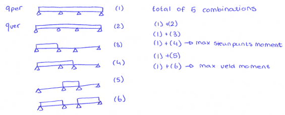
Fig. 14.9 5 different load combinations#
The different combinations correspond to situations j (for own weight) + a choice from j to n in Beams with multiple supports. Just check that:
j = 2 (but therefore also 1, given the guaranteed own weight)
k = 6
l = 5
m = 4
n = 3
(ii) Using the tables of Beams with multiple supports the dimensional load combination for the field moment and support point moment.
Answer
When you remove from Beams with multiple supports the rows and columns that are not needed for the moments in this assignment, it produces Table 14.5. For the moments, multiply the values in Table 14.5 by \(q*L^2\). For X = 0, \(L = 5 m\). The load factors \(\mathbf{1.1}\) for \(\mathbf{q_{per}}\) and \(\mathbf{1.35}\) for \(\mathbf{q_{ver}}\) are only included in the final summation and initially omitted.
Type |
M(1) |
M2 |
M(2) |
M3 |
M(3) |
|---|---|---|---|---|---|
j |
0.0800 |
-0.1000 |
0.0250 |
-0.100 |
0.0800 |
k |
0.1013 |
-0.0500 |
-0.0500 |
-0.0500 |
0.1013 |
l |
-0.025 |
-0.0500 |
0.0750 |
-0.0500 |
|
m |
0.0735 |
-0.1167 |
0.0535 |
-0.0333 |
|
n |
0.0939 |
-0.0667 |
-0.0250 |
0.0167 |
For the permanent load (type j), which consists of the deadweight of the concrete beam and the floor, \(q = G_{concrete beam,shaft,B} + G_{floor,shaft,B} = 1.75 + 11.655 = 13.405 kN/m\). Combining the previous factor from Table 14.5, \(L = 5 kN/m\) and q yields Table 14.6.
Type |
M(1) |
M2 |
M(2) |
M3 |
M(3) |
|---|---|---|---|---|---|
j |
26.81 |
-33.51 |
8.38 |
-33.51 |
26.81 |
For the variable load (types j to n), which consists of the deadweight of the concrete beam and floor, \(q = Q_{inside,axis,B} = 7.875 kN/m\). Combination of the previous factor from Table 14.5, \(L = 5 kN/m\) and q yields moments_changeable.
Summation of the permanent load type j with the various types for the variable load yields the moments in Table 14.7. In this summation, the load combination type refers back to the variable load, given that the permanent load is always j. The load factors \(\mathbf{1.1}\) for \(\mathbf{q_{per}}\) and \(\mathbf{1.35}\) for \(\mathbf{q_{ver}}\) are now taken into account.
Type |
M(1) |
M2 |
M(2) |
M3 |
M(3) |
|---|---|---|---|---|---|
j |
50.754 |
-63.442 |
15.860 |
-63.442 |
50.754 |
k |
56.415 |
-50.153 |
-4.073 |
-50.153 |
56.415 |
l |
22.846 |
-50.153 |
29.150 |
-50.153 |
29.491 |
m |
49.026 |
-67.880 |
23.435 |
-45.714 |
29.491 |
n |
54.448 |
-54.591 |
2.571 |
-32.425 |
29.491 |
(iii) Calculate the maximum moments.
Answer
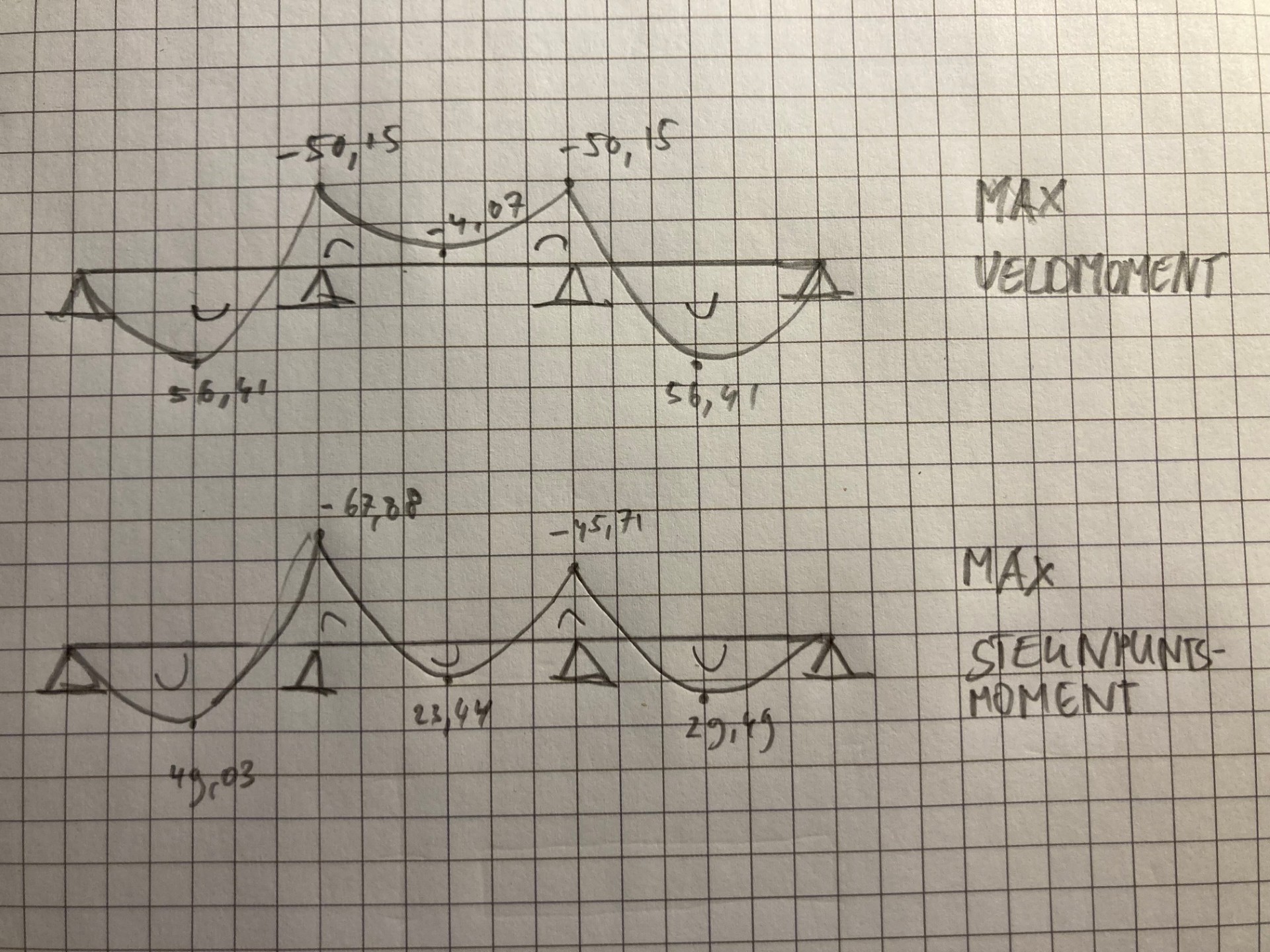
From the Table 14.7 follow the maximum values:
\(\mathbf{Maximum field moment = 56.41 kNm}\) for \(\mathbf{combination kNm}\)
\(\mathbf{Maximum support point moment = -67.88 kNm}\) for \(\mathbf{combination_m}\)
(iv) Draw the moment line for the maximum field moment and the moment line for the maximum fulcrum moment.
\(\mathbf{\text{Question i}}\)
For the concrete column at the intersection of axis B and axis 2, give the dimensional load combination for the maximum compressive force (calculation value \(R_d\), i.e. including load factors). Use Table 14.8. In addition, the following loads are of interest:
\(\textbf{EG Concrete Column [kN/m]}\): Determined in assignment d
\(\textbf{Permanent Floor Load [kN]}\): Use Quick Reference to determine reaction force of beam assignment h
\(\textbf{Variable Floor Load [kN]}\): Use Quick Reference to determine reaction force of girder assignment h
X |
EC Steel Column [kN/m] |
Permanent Roof Load [kN] |
Variable Roof Load [kN] |
|---|---|---|---|
0 and 1 |
0.60 |
13.79 |
20.78 |
2 and 3 |
0.74 |
16.01 |
23.75 |
4 and 5 |
0.91 |
18.29 |
23.75 |
6 and 7 |
1.07 |
20.08 |
23.75 |
8 and 9 |
1.27 |
22.31 |
23.75 |
In the case, X = 0, so EG Steel Column = 0.60 [kN/m], Permanent Roof Load = 13.79 [kN] and Variable Roof Load = 20.78 [kN].
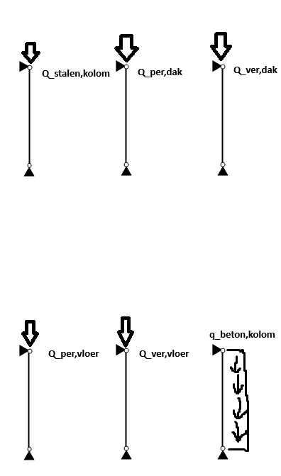
(i) Draw load on structure diagrams per individual load
(ii) Calculate the \(\textbf{measured design calculation value of the compressive force}(R_d)\)
Answer
The compressive force consists of a summation of different forces icm load factors:
Steel column own weight
\(R_{steel,column} = h * q_{steel,column} = 3 * 0.60 = 1.80\) \(kN\)Permanent roof load
Given: \(R_{per,roof} = 13.79\) \(kN\)Changing roof load
Given: \(R_{ver,roof} = 20.78\) \(kN\)Own weight concrete column
\(R_{concrete,column} = h * q_{concrete,column} = 4 * 0.5625 = 2.25\) \(kN\)Permanent floor load From Beams with multiple supports, the relevant information is that of R2 (overlay reaction 2), given that it is axis B2 (see Fig. 14.2). These factors needed are stored in Table 14.9. This factor must be multiplied by \(q*L\).
Type |
R2 |
|---|---|
j |
1.1000 |
k |
0.5500 |
l |
0.5500 |
m |
1.2001 |
n |
0.6501 |
Given that this is a permanent load, only type j is relevant. Earlier, \(q = 13.405 kN/m\) was already established. So the reaction force of the permanent floor load is: \(R_{per,floor} = factor * q * L = 1.1 * 13.405 * 5 = 73.7275\) \(kN\)
Variable floor load
Given that this is a variable load, only the largest, type m, is relevant. Earlier, \(q = 7.875 kN/m\) was already established. So the reaction force of the permanent floor load is: \(R_{ver,floor} = factor * q * L = 1.2001 * 7.875 * 5 = 47.254\) \(kN\).
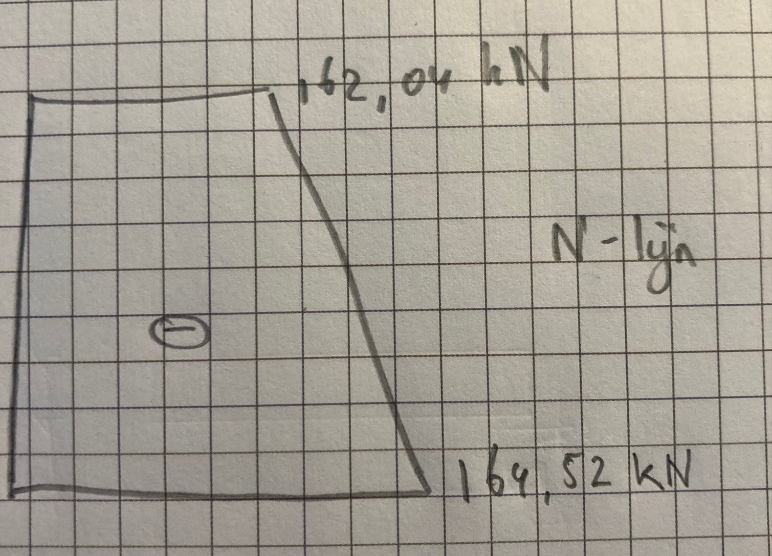
The load factors \(\mathbf{1.1}\) for \(\mathbf{q_{per}}\) and \(\mathbf{1.35}\) for \(\mathbf{q_{ver}}\) are now included. This yields the following reaction force at the top of the column: \(R_{to,above} = 1.1*q_{per} + 1.35*q_{ver}\) \(= 1.1*(R_{steel,column} + R_{per,roof} + R_{per,floor}) + 1.35*(R_{ver,floor})\) \(= 1.1*(1.80 + 13.79 + 73.7275) + 1.35*(47.254) = 162.04\) \(kN\)
Note
The changeable roof load disappears, given that the changeable floor load is greater and is therefore taken characteristically!
At the bottom of the column, the load from the column’s own weight is added: \(R_{tot,bottom} = R_{tot,top} + 1.1*R_{concrete,column}\) \(= 162.04 + 1.1*2.25 = 164.52\) \(kN\)
(iii) Draw the N-line
Appendix A - Design drawings#
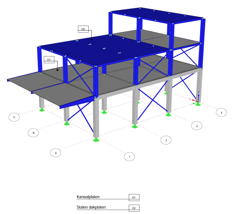
Fig. 14.13 3D model including hollow core slabs and steel roof panels.#
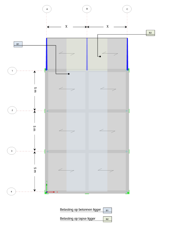
Fig. 14.14 Floorplan, first floor.#
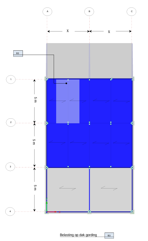
Fig. 14.15 Floorplan, second floor.#
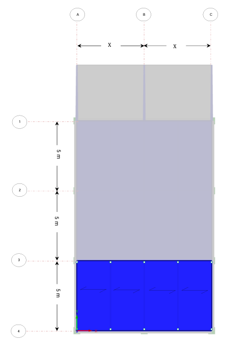
Fig. 14.16 Floorplan, roof.#