
16.1. Global dimensioning beam#
Note
The calculations serve as examples for educational purposes and not as guidance for practice.
The cross-section dimensions (height x width) of a beam depend on the forces acting on it and on its span. To provide an initial estimate of the dimensions, estimation rules (‘rules of thumb’) or design diagrams are available. These rules of thumb are useful for a first approximation only and are mainly intended for common structures with regular loads. The more extreme the structure or the load placed on it, the more inaccurate the estimation rule becomes.
For the office that serves as our example building, we want to dimension and check the first-floor beam(s) on axis 3 on the schematic load-bearing construction floor plan in the figure below.
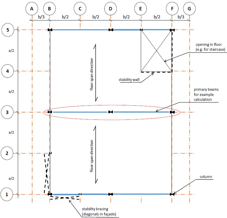
Fig. 16.1 Schematic load-bearing floor plan, first floor office building. In our example, a = 8 m and b = 6 m.#
The beam on axis 3 as shown in the floor plan is interupted by the column on D3. This means that the structural scheme of axis 3 is the top one from the two possible schemes shown in the image below. The lower one would have been a continuous beam supported in the middle.
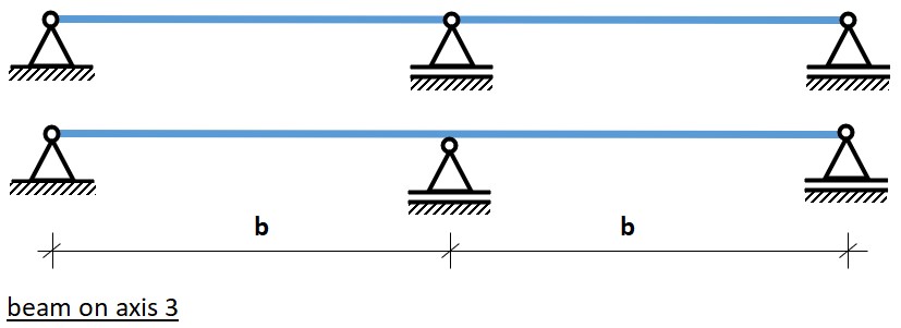
Fig. 16.2 Structural scheme of the beam(s) on axis 3. We choose the top one, with two single spans, and not a continuous beam on three supports. This has the advantage that the column can be continued over multiple floor levels.#
In Concrete - rules of thumb we can find rules of thumb for the estimation of height and width of a reinforced concrete beam. As we chose for two single spans, and the beam is traditionally reinforced and not prestressed the rule of thumbs gives:
The weight per linear meter is now determined by multiplying the cross-sectional area \(b\) × \(h\) m² by the density \(ρ\) kg/m³, and then multiply the result by the gravitational acceleration \(g = 9.81\) m/s², often rounded to \(10\) m/s² for early design calculations. For reinforced concrete the density is around \(2500\) kg/m³. The weight per linear meter \(q_g\) becomes: \(q_g = b × h × ρ × \frac{10}{1000}\) kN/m. (NB: \(b\) and \(h\) in meters!)
For a rectangular cross-section, we can easily calculate the resistance moment (also known as section modulus) \(W\) and the quadratic area moment \(I\). We need these later to verify stresses and deflection:
First, we need to estimate the dimensions. For the concrete structure, we use a cast in-situ (cast on site), non-prestressed concrete beam. Let’s assume a strength class C20/25. According to the rules of thumb above, the height h would be equal to approximately:
For the width, we choose:
The weight per linear meter becomes: \(q_{self} =0.30 × 0.60 × 2500 × 10/1000 = 4.5\) kN/m.
Tip
You can skip this part if you want to directly determine loads and reinforcement, as in nearly all cases tensile strength is exceeded and reinforcement is required. Continue with ‘Determining loads on the beam’. However, if you also want to check deflections, then continue here, as you will need \(I_y\).
We can now calculate \(I\) and \(W\) using the above equations.
Note that the units for \(I\) and \(W\) are \([10^4 \ mm^4]\) and \([10^3 \ mm^3]\), a notation often also found in profile tables which allows you to get some sense of the order of magnitude. It is strongly advised to use this same notation. They stem from the non-SI units \([cm^4]\) and \([cm^3]\). The values for strength (characteristic tensile strength) and modulus of elasticity can(for uncracked concrete) be obtained from the concrete tables in the Material Properties Concrete section. It is advisable to neatly organize the beam data, for example, in a table as shown below.
Height \(h_{beam} \ [mm]\) |
Area \(A \ [mm²]\) |
Weight \(q_G \ [N/mm]\) |
Moment of Inertia \(I_y \ [10⁴ \ mm⁴]\) |
Section modulus \(W_y \ [10³ \ mm³]\) |
Strength class |
Char. tensile strength \(f_{ctk} \ [N/mm²]\) |
Youngs modulus (uncracked) \(E_{cm} \ [N/mm²]\) |
|---|---|---|---|---|---|---|---|
600 |
600x300 |
4.5 |
540 000 |
18 000 |
C20/25 |
1.5 |
30 000 |
Note
It is good to notice that for the strength we did not use the compressive but the characteristic tensile strength of the concrete, as the latter is rather lower than the former. In a beam loaded on bending, the tension stresses in the part of the concrete generally that is under tension (that is: below the neutral line for a positive bending moment) are much higher than the tensile strength, so that reinforcement will need to take over, as we will see below. For this reason we will also provide a rule of thumb to approximate the amount of bending reinforcement necessary. To save time, you could even skip the check on bending stresses and directly move on to determining the reinforcement.
Determining loads on the beam#
The load on the beam consists of three components:
\(q_{self}\) = self-weight of the concrete (calculated above)
\(q_{resting}\) = other permanent loads, such as self-weight of the floor, ceiling, ducts and pipes, floor finishings, etc.
\(q_{imposed}\) = imposed variable load, such as people or furniture
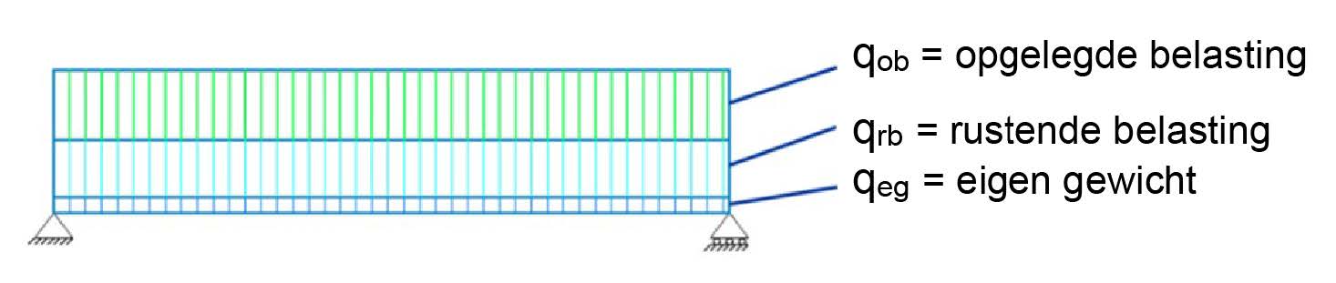
Fig. 16.3 Loads on the beam#
\(q_{self}\) and \(q_{resting}\) together form the characteristic permanent load \(G_k\). The imposed variable load \(q_{imposed}\) is the characteristic variable load \(Q_k\) (using the abbreviations from the Eurocode). For beam verification, the loads must be calculated per linear meter on the beam, unless the load is applied as a point load on the beam. We assume a uniformly distributed load.
Note
To determine the amount of floor area resting on our beam, we use the schematic load-bearing floor plan (e.g. Fig. 16.5 below). On it, we have shaded the area supported by the beam. All elements in the shaded area, including the weight of any secondary beams, must be included in the load. On this load-bearing floor plan we also show the actual dimensions.
The resting load consists of the weight of the floor structure, including the weight of any finishing layer, ceiling, installations (air ducts, water pipes, electricity and data cables, also know as building services) suspended from the floor, or included in the floor structure, etc. All these loads are given in kN/m² or have to be converted into these units. For example, for a concrete overlay, the volumetric mass kg/m³ should be converted to the volumetric weight kN/m³: 1 kg/m³ corresponds to 0.01 kN/m³. The volumetric weight should is then multiplied by the layer thickness to arrive at the load in kN/m²:
\(\Rightarrow\) Load in [kN/m²] = layer thickness in meters multiplied by the specific weight in [kN/m³].
In the figure below, the elements of the resting load for the construction are schematically depicted.
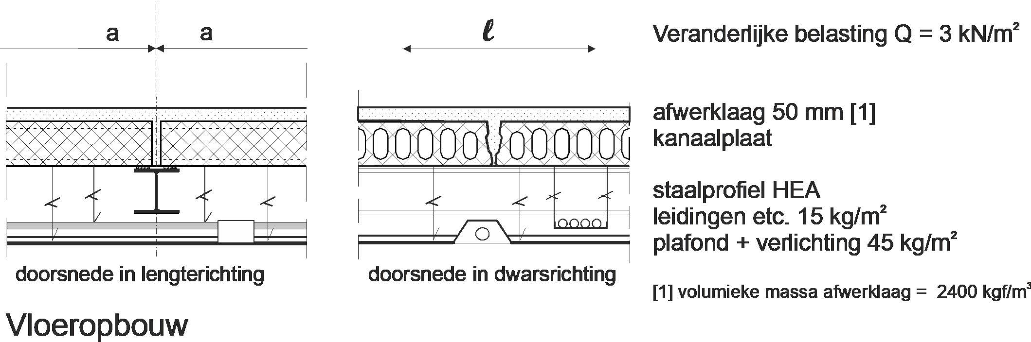
Fig. 16.4 Cross-section of hollow-core concrete slab system and steel beam#
From top to bottom, we first see a finish layer of 50 mm. The volumetric mass of the finish layer material (usually a mixture of sand and cement) is 2000 kg/m³.
\(\Rightarrow\) Weight of finish layer = \(0.05 × 2000 = 100 \ [kg/m²]\) \(\Rightarrow\) \(0.01 × 100 \ [kg/m²] = 1.0 \ [kN/m²]\).
Next, we see the precast concrete floor slab. The dimensions of these slabs depend on the span and load on the slabs and on the building function. When these are known, the manufacturer can easily determine which slabs are needed. The span here is 8 meters (that is the center-to-center distance of the main beams!). Considering the cross-sections, it is easy to see that besides an imposed load of \(3\) kN/m², the floor slab must also support the finish layer, pipes, ceiling, and lighting.
The mass of ceiling and installation totals \(15 + 45 = 60 \ [kg/m²]\).
The weight then becomes \(\Rightarrow\) \(0.01 × 60 = 0.6 \ [kN/m²]\).
The total (variable + permanent) load on the floor slabs (excluding the floor slabs themselves, excluding partial safety factors) then becomes \(\Rightarrow\) \(3.0 + 1.0 + 0.6 = 4.6 \ [kN/m²]\).
These data can be provided to the manufacturer. For a design calculation, the manufacturer often provides tables or graphs. In section Section 10.6, such a graph is shown. On the vertical axis, we plot the load of 4.6 kN/m² and on the horizontal axis the span of 8 m. The intersection of both lines lies between the slab with a thickness of 150 mm and that with a thickness of 200 mm. Therefore, for our building, we need a slab thickness of 200 mm. The weight of this slab is 3.1 kN/m².
So, the total permanent load (without partial safety factor) of the floor is 3.1 + 1.0 + 0.6 = 4.7 kN/m² and the variable load is 3.0 kN/m².
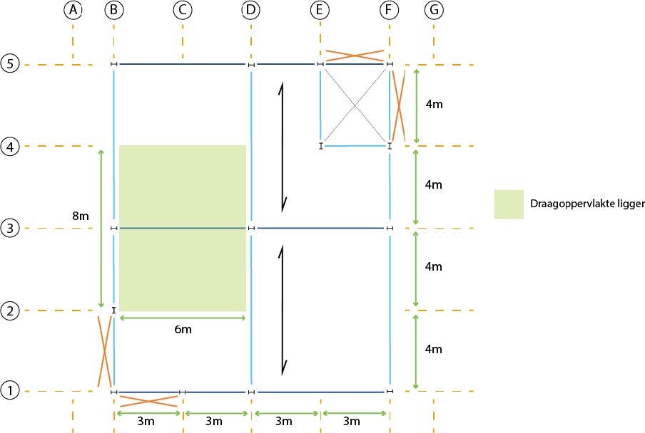
Fig. 16.5 The shaded area of the floor is the area supported by the beam on axis 3#
The found load in kN/m² needs to be converted to an equally distributed load on the beam, which is a load per linear meter of beam [kN/m]. To determine its magnitude, we use the schematic load-bearing floor plan. On the beam, we mark a distance of 1 meter and shade the area supported by this meter of the beam. The size of this area is equal to two times the half center-to-center distance of the beams times 1 meter.
The load per linear meter [kN/m] then becomes \((a/2+a/2 \ [m])\) x the load per square meter [kN/m²].
For edge beams (axis 1 and 5), of course, only half the center-to-center distance applies, as they are only loaded by floor slaps from one side.
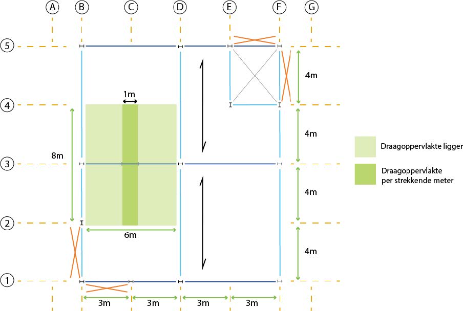
Fig. 16.6 The dark green area represents the load per linear meter on the beam on axis 3#
Note
The imposed load for each function is prescribed in the Eurocodes. The building has an office function. As already assumed earlier, the corresponding imposed load is 3 kN/m². To make this a load per running metre of girder in kN/m, it should also be multiplied by two times half the centre-to-centre distance.
For the central concrete beam on axis 3 with a center-to-center distance of 8 meters, and including the weight of the beam itself, the characteristic permanent load \(G_k\) is:
For the characteristic variable load \(Q_k\) on the concrete beam, the following applies:
Check for ULS (strength)#
With the loads determined above, we can perform the strength and stiffness check. For strength, we need to verify the Ultimate Limit State (ULS). For a beam in steel or timber supported at two points, we would now determine the maximum occurring bending stress \(\sigma_{m;d}\), which must be less than or equal to the bending strength: \(\sigma_{m;d} \le f_{m;d}\). However, for a concrete beam under regular loads as the one discussed in this chapter, we can safely assume the concrete will crack, as bending tensile strength is very limited. Steel reinforcement will take these tensile stresses, as shown in Section 10.2. Therefor, a smarter step is to directly determine the necessary cross-sectional area of the steel reinforcement \(A_{s;required}\) that is required to transfer the force \(N_s\) in Fig. 10.5 and see if this fits in the cross-section dimensions of the beam chosen earlier.
First we need to calculate the maximum bending moment which for this simple case is:
where \(l\) is the length of the beam [m] and \(q\) is the total line load [kN/m]. Be consistent with the units!
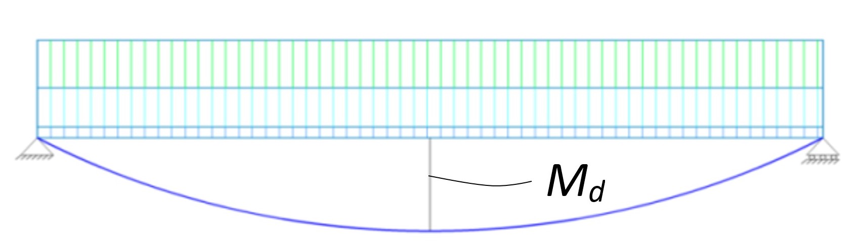
Fig. 16.7 Maximum moment for beam on two supports and equally distributed load.#
For the Ultimate Limit State (ULS), we need to apply the so-called Fundamental Load Combination. The loads must be multiplied by a partial factor \(\gamma_{f}\) to ensure additional safety. These factors depend on the consequence class of the building and the nature of the load. \(\gamma_{G}\) and \(\gamma_{Q}\) are the partial factors for the permanent load and the variable load, respectively.
According to Eurocode 1990, the permanent load may be reduced by a reduction factor \(ξ\). This is set at 0.89 in the National Annex to the Eurocode. For most buildings (including offices), \(\gamma_{G}\) is 1.35 and \(\gamma_{Q}\) is 1.5. The partial factor for the permanent load is multiplied by the reduction factor: \(0.89 × 1.35 = 1.2\) (the value of the former load factor for the permanent load). We will use this value as the partial factor for the permanent load. Therefore, for the office building: \(q_{ULS} = 1.2 \cdot q_G + 1.5 \cdot q_Q\). With these quantities, we can calculate the moment and thus the bending stress, and then check the strength by performing the unity check (U.C.):
Using Method 1 from Section 10.2 we find:
If we use reinforcement bars with a diameter Ø20 (\(A_s=314\) mm² each) we would need \(n=1852/201=5.9\) bars, which rounds (always up) to 6. We suspect that the distance between the rebar becomes too small to let concrete through:
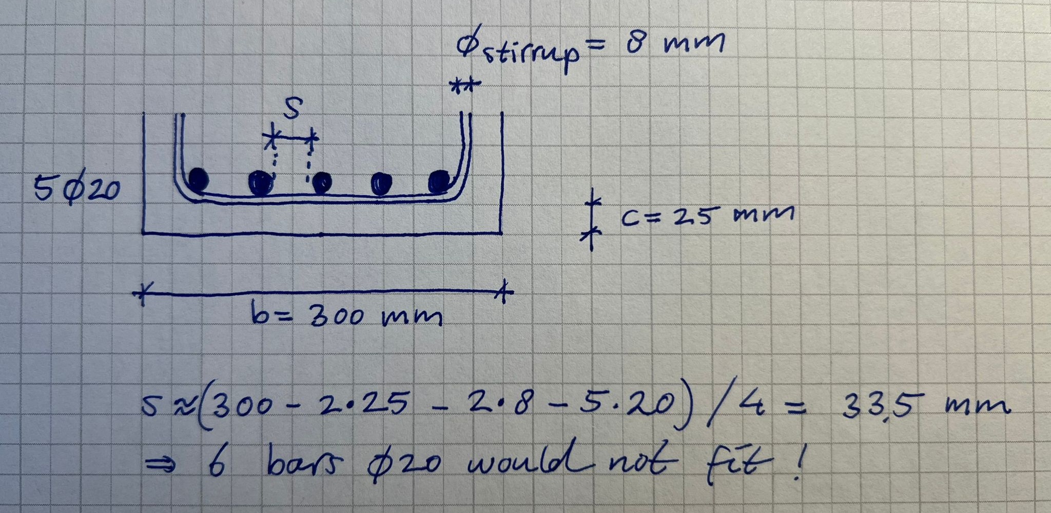
Fig. 16.8 Sketch of rebar distance (here only 5 bars are used)#
We suspect that we need a slightly higher cross-section than the one based on the used rule of thumb \(h=L/10\). We could also make the cross-section wider (increase b) but this seems a bit waste of concrete if it just serves to increase rebar distance. Let’s increase \(h\) to \(h=L/9=650 mm\) which should increase the lever arm and make lead to less reinforcement. The self weight increases with a factor \(650/600=1.08\) which for now will be neglected, as the self-weight of the beam is only small proportion of the total load \(q_d\).
Check ULS
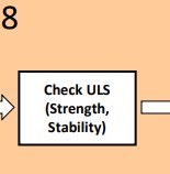
Then the unity check is performed for the ULS state.
Check for SLS (stiffness)#
To check the stiffness, we examine the Serviceability Limit State (SLS), also known as the stiffness of the beam. In section Serviceability Limit States section, you will find all the provisions applicable to this limit state. The stiffness determines the amount of deflection: the stiffer the beam, the less the deflection. The formulas for the deformation of standard cases (reminders) can be found in the Mechanics section. For a simply supported beam, the formula is:
For the SLS, there are two checks: the additional deflection \(w_{in}\) and the deflection in the final state \(w_{max}\). The requirement for the maximum deflection is an aesthetic one, while that for the additional deflection is more a matter of comfort: does one feel safe if a beam deflects too much. Moreover, an excessive \(w_{inf}\) can lead to damage in walls placed on the floor, while the finishing layer of the floors could also crack.
The maximum deflection \(w_{max}\) is the total deformation \(w_{fin}\) due to the load, including any creep, minus any camber provided:
A camber is an upward curve provided in advance to reduce the deflection due to the permanent load \(w_{G}\) = \(w_{on}\). The final deformation \(w_{fin}\) is the sum of the instantaneous deformation and the additional infinite deformation:
The additional infinite deflection \(w_{inf}\) is the deformation that occurs due to the variable load and any creep. Creep occurs in materials such as wood and concrete under long-term load. This is the permanent load and that part of the variable (imposed) load that is almost permanently present:
There is a relationship between creep and the permanent and quasi-permanent load. The creep is expressed as:
Here, \(k\) = creep factor and \(\psi_2\) = quasi-permanent load factor.
This is summarised in the figure below.
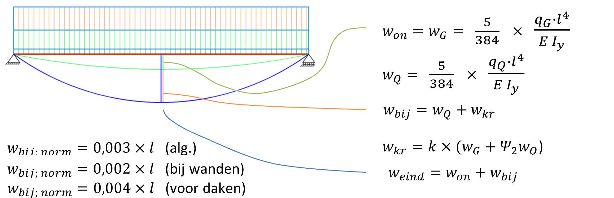
Fig. 16.9 Instantaneous and infinite deflection in final state.#
The factor \(\psi_2\) depends on the building function. In the Loads section, the factors for all building functions are provided. For offices and residential buildings, \(\psi_2 = 0.3\). The factor \(k\) depends on the material. In the Material Properties section, the factors for different materials are given. Steel has a creep factor \(k = 0\) and thus \(w_{kr} = 0\). For wood, \(k = 0.8\) (climate class 2), making:
In reinforced concrete, deflection is increased not only by creep but also by cracking in the tension zone of the concrete. The calculation of this is quite complex and exceeds the scope of this guide. A reasonable approximation for dry concrete is obtained with a creep factor \(k\) = 3, making:
In steel, the modulus of elasticity is independent of the strength class. In wood, it depends not only on the strength class but also on the fibre direction and the limit state. For the deflection of a wooden beam, we must use \(E_{0,mean}\), and for laminated beams, \(E_{0,gl,mean}\) (see Material Properties Wood). In concrete, the modulus of elasticity depends on the strength class and the limit state. For deflection (SLS), we must use the value for \(E_{cm}\) (see the section Material Properties Concrete).
For a floor beam, the general requirement is:
If the beam is located near a wall or in the facade, then:
The unity check thus becomes:
If the U.C. \(>\) 1, a heavier profile must be chosen. For the required moment of inertia \(I_{necessary}\) of the new profile, the following applies:
The formulas for \(W_{necessary}\) and \(I_{necessary}\) can also be used for both ULS and SLS if the U.C. \(<<\) 1. A slimmer, thus cheaper and more sustainable profile can suffice. The larger of the two values of U.C. is then obviously the starting point.
We also note that for the maximum deflection of a floor:
For a roof beam, both \(w_{inf}\) and \(w_{fin}\) must be less than \(0.004 \cdot l\).
Note
A roof terrace must be considered as a floor!
Note
For a concrete beam, we must account for creep (and a cracked cross-section). Here, #\textbf{k=3}\( and for an office, \)\psi_2 = 0.3\(. For concrete strength class C30/37, \)E_{c,m} = 33000 [N/mm^2]$. The deflection due to the permanent load is:
\(w_G = \frac{5}{384} \cdot \dfrac{q_G \cdot l^4}{E_{cm} \cdot I_y} = \frac{5}{384} \cdot \dfrac{(4.73 [kN/m] + 39.2 [kN/m]) \cdot 6000 [mm^4]}{33000 N[/mm^2] \cdot 6251.2 \cdot 10^6 [mm^4]} = 3.6 [mm]\)
The deflection due to the variable load is:
\(w_Q = \frac{5}{384} \cdot \dfrac{q_Q \cdot l^4}{E_{cm} \cdot I_y} = \frac{5}{384} \cdot \dfrac{24 [kN/m] \cdot 6000 [mm^4]}{33000 N/mm^2 \cdot 6251.2 \cdot 10^6 [mm^4]} = 2.0\ mm\)
The additional deflection can now be determined:
\(w_{inf} = w_Q + k \cdot (w_G + \psi_2 \cdot w_Q) = 2.0 [mm] + 3 \cdot (3.6 [mm] + 0.3 \cdot 2.0 [mm]) = 14.6 [mm]\)
The deflection requirement and the unity check:
\(w_{inf,req} = 0.003 \cdot l = 0.003 \cdot 6000 [mm] = 18 [mm]\)
\(U.C. = \dfrac{w_{inf}}{w_{inf,req}} = \dfrac{14.6 mm}{18 mm} = 0.81 \leq 1\)
The beam amply meets the deflection requirement, so we see that strength is the governing factor. With strength class C35/45, a beam \(b \cdot h = 300 \cdot 600 [mm^2]\) meets the requirement. Usually, the cross-sectional dimensions are rounded to multiples of 50 mm. Therefore, we choose the beam with strength class C35/45. This beam has a weight:
\(0.3 [m] \cdot 0.6 [m] \cdot 25 [kN/m^3] = 4.5 [kN/m]\)