
1. The design process#
The design process is part of the life cycle of a structure, consisting of the idea-phase, the design phase, the construction phase, the use and maintenance phase, and the end-of-life phase (the latter possibly being reuse). The structural engineer primarily, but not solely, acts in the design phase. Especially for starting structural designers who mostly have background knowledge in structural mechanics and mathematics, it is necessary to realise that designing is fundamentally different from solving equations. In most cases, structures are complex systems, developed according to structural concepts and consisting of multiple subsystems. This complexity makes the design process less straightforward than just mechanics or mathematics, and a problem solving strategy is needed. One of these strategies is to break down the process into smaller steps, which are iteratively followed to reach a (not ‘the’) solution.
This iterative process is illustrated by the following image:
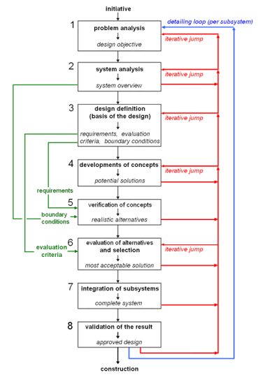
Fig. 1.1 Flowchart of the structural design developed by Voorendt et al (2015)#
The terms initiative, project definition, concept development, preliminary design, and verification of structural safety will be explained shortly below.
1.1. Initiative#
The client initiates a construction project or structure. The designer, being advised by an architect, determines design goals. The design goal is a general description of the desired result of the design and execution process. After determining the design goal, the designer can study different aspects of the project. For example: the location, the budget and functional requirements. When all aspects are determined, they are integrated and evaluated. The final step of this phase is to check whether the project is financially and logistically feasible. If this is not the case, the design goals need to be adjusted. The concequence of this is that the whole cycle starts again (aspects, integration, evaluation and check).
Result
A Program of Requirements (PoR) formulated by the client
1.2. Design definition#
To define the project, one first drafts a plan of action (strategy). This determines how to proceed in this phase, what the results should be and the criteria to which the result of this phase should be compared. Just like in the previous phase various aspect studies need to be done. Eventually this leads to the formulation of a report containing all basic assumptions concerning the structural design. This forms a supplement to the PoR.
Result
A Program of Requirements supplemented with structural assumptions
1.3. Development of concepts#
In this phase too several studies have to be performed. The designer makes several structural concepts. Examples of structural concepts can be found elsewhere on these pages. To make a sensible design, she first analyses the force flow in both horizontal and vertical direction. Also the ability of the structure to retain its shape and place is investigated as well as the connections between different elements and parts of the building. After feedback from the structural assumptions at least two of the concepts are chosen for further analysis.
Although the load bearing structure is now designed, this phase is not yet finished. Finally the designer needs to look into possible façades and roof elements. Now a choice can be made between the different concepts based on a multi criteria analysis. The criteria are based on the PoR and structural assumptions.
Result
Design sketches of the different concepts with a reasoned choice of a design
Estimation of dimensions#
With the aid of design tools (rules of thumb, diagrams and tables) the overall dimensions of the structure (including stability measures) are estimated and critical connections are studied for feasibility. The sections in the Structural Design Essentials on different materials contain information on structural elements (such as precast conrete beams, hollow core slabs etc.) and tables with available (steel) profiles to come to reasonable dimensions. Already in this stage it is wise to orient oneself to different foundation possibilities as the foundation design will influence the above-ground structure and the other way around. The section on foundations provides the necessary information. In case of buildings, also the building envelope deserves some attention. For operable bridges, mechanical parts may require attention. Use the different examples given in the later chapters.
Result
General preliminary structural design, general dimensions of the main structure. Ideas on fabrication, erection, foundation, mechanical parts and façades.
Check of strength, stiffness and stability#
As next substep a further analysis of the strength, behaviour of the structure is made. Also the stability is checked, and necessary stability measures are added. To do this, quick calculations are made with simplified load combinations for the Ultimate Limit State (ULS) and Serviceability Limit State (SLS). The section on mechanics offers the necessary formulas and ‘forget-me-nots’. More attention is given to the foundation of the structure. Calculate the total vertical load and design a transition structure (which transfers the loads from the main load bearing structure to the foundation). Also a further analysis is made of the possible façades, roof elements and other building finishes needs to be made. How are the building finishes connected to the load bearing structure?
Result
A structure which retains its place and shape under loading with dimensioned structural parts. A conceptual design of the foundation, building envelope, fabrication, erection and structural details.
1.4. Validation (or: verification) of the structural design#
The final preliminairy design of which the final dimensions are now determined, has to be checked with a structural code. In Europe this is the Eurocode. The different sections on steel, timber, concrete and foundations contain the necessary information to perform the check.
Result
A structural design which not only meets the needs of the client and other stakeholders but also complies with the applying structural code.
1.5. Diagram of workflow during the structural design#
Klompenhouwer (2015) has developed a flowchart that focusses on the smaller substeps of 1.3 and their logical order. The figure is shown below. It can be useful as a more detailed guideline. A PDF-version of the same figure can be found here and a Dutch version here.
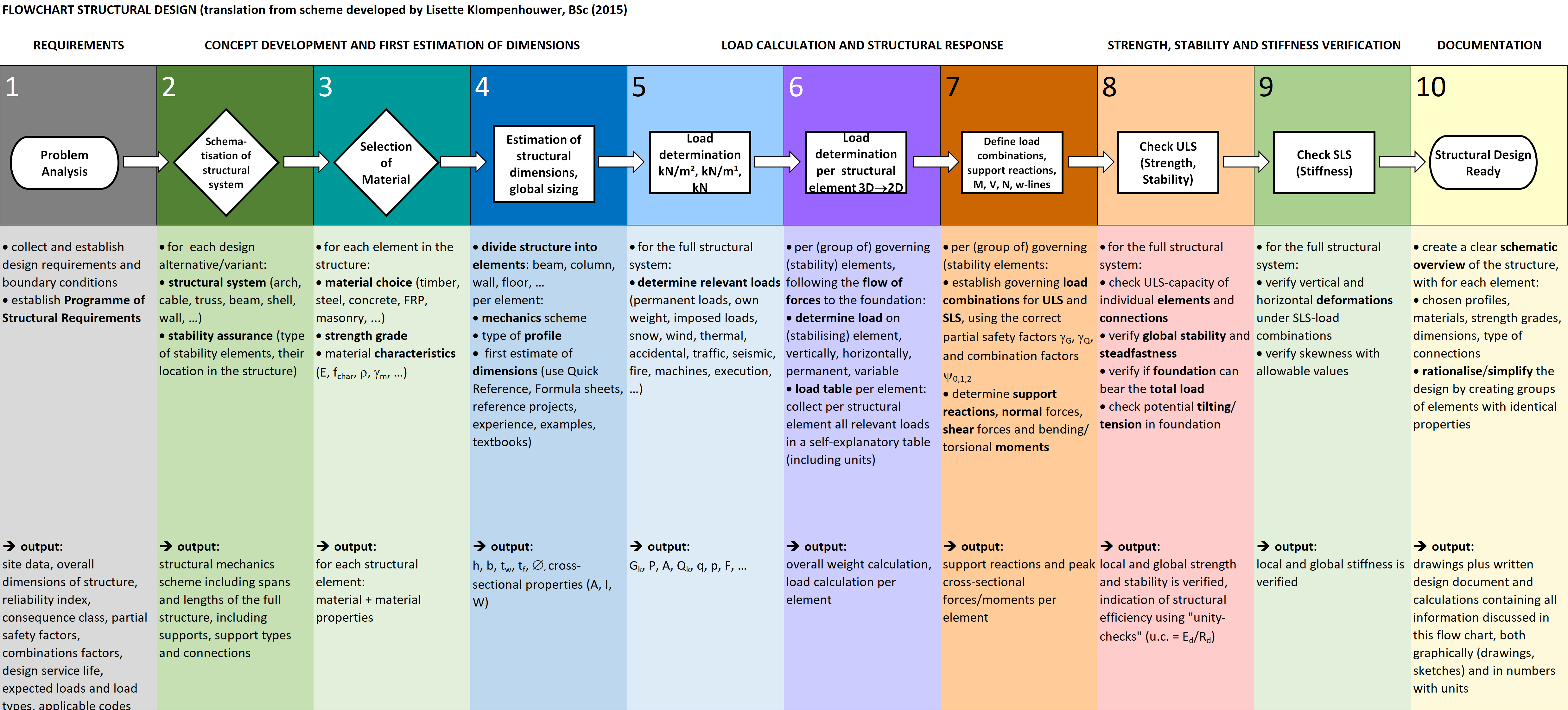
Fig. 1.2 Flowchart of the structural design developed by Klompenhouwer (2015)#