
4.1. Technical drawings#
To make a clear technical drawing it is wise to follow the steps depicted below. Every step discribes shortly what should be done. For more in formation how it should be done reference is made to the lecture notes ‘Technical Drawings’ (CT1052-09). The steps below are mainly applicable for handdrawings, but are also useful for CADdrawings.
Size and header#
Paper size can vary from A4 to A0. Most of the time A3 is chosen. Draw a frame which does not touch the edges of the paper.
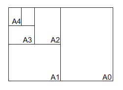
Fig. 4.1 Varying paper size.#
Header#
The header contains information on the drawing, drawer, scale and units.
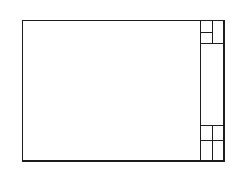
Fig. 4.2 How to draw the header for technical drawings.#
Layout#
A technical drawing contains a minimum of three elevations or corsssections. The elevation containing most information is placed a the top left position. The other elevations are now determined with third angle projection (Dutch: Amerikaanse projectie). If additional elevations, sections or detail drawings need to be added, they are placed at the bottom right corner of the paper.
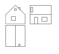
Fig. 4.3 How to draw the lay-out for technical drawings.#
Scale#
Only scales 1:1, 1:2 and 1:5 or multiples of 10 of these are allowed. Always try to draw the object as large as possible on the chosen paper. Remember however that also some space will be used for dimensions and text. If one or more elevations (details!) have a different scale, mention this in the title below this particular elevation.
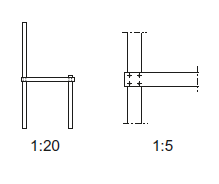
Fig. 4.4 How to draw the scale for technical drawings.#
Contours#
With a pencil grid lines, centre lines and datum lines can be drawn. After this, draw the contours of the object. If necessary, some changes to the layout or scale of the drawing can be made.
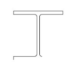
Fig. 4.5 How to draw the contours for technical drawings.#
Objects#
The object is drawn in detail.

Fig. 4.6 Technical drawing of an object.#
Dimensions#
How? Dimensions are indicated by a dimension line and two auxilairy lines indicating the length to be dimensioned. The intersection between the lines is indicated with a little diagonal line, dot or arrow. The auxilairy lines do not touch the object. The value of the dimension is written in the middle of the dimension line, but can be placed on a leader if there is a lack of space. Heights are usually measured in relation to a reference level and are indicated with an arrow. The units used depend on the size of the object, but can only be: micrometers, millimeters, meters and kilometers.
What? Only the dimensions necessary to understand and built the object need to be shown. Where possible, use centre lines.
Where? Place dimensions as much as possible to the right and below the elevation which shows the important component the clearest. Deviations of this ‘general rule’ are only allowed if this clarifies the drawing. If multiple dimensions are shown on one line, a summation must always be added, with an extra dimension line.
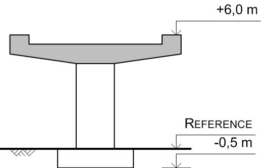
Fig. 4.7 Dimensioning in technical drawing, height levels.#
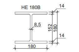
Fig. 4.8 Dimensioning in technical drawing, details.#
Hatching#
To indicate used materials cross sections are hatched. See gd|b for different types of hatches. Note that the hatch to be used depends on the scale of the drawing. If two components meet which must be hatched in the same way, the hatch is rotated 90°. This is only applicable to hatches consisting of diagonal lines.
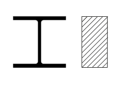
Fig. 4.9 Hatching in technical drawings.#
Lines#
Now the different lines in the drawing need to be given the correct thickness and type. For an overview of the different types and thicknesses and their applications, see the lecture notes on Technical Drawing.
Fig. 4.10 Different type of lines in technical drawings.#
Text#
Finally, if necessary with the aid of leaders, texts are added. Elevation titles need to be placed below the object, aligned to the left. If this particular elevation differs in scale of the rest of the drawing mention this in the elevation title. Do not use abbreviations in titles.
Fig. 4.11 Text in technical drawings.#