
7.2. Reinforcement#
This paragraph contains information on the material properties of reinforcement steel.
Strength and stiffness#
Material properties (bars)#
Steel Grade |
Tensile Strength \(( f_{t;k} )\) [N/mm²] |
Yield Stress \(( f_{y;k} )\) [N/mm²] |
Strain at Maximum Load \(\varepsilon_{su}\) [‰] |
|---|---|---|---|
FeB 400 HWL, HK |
400 |
350 |
4.00 |
FeB 500 HWL, HK |
500 |
435 |
3.25 |
FeB 500 HKN |
500 |
435 |
2.75 |
Material properties (nets)#
Steel Grade |
Tensile Strength \(( f_{t;k} )\) [N/mm²] |
Design value tensile strength \(( f_{y;k} )\) [N/mm²] |
Strain at Maximum Load \(\varepsilon_{su}\) [‰] |
|---|---|---|---|
FeB 500 HKN, HWN |
500 |
435 |
2.175 |
Reinforcement areas for beams and columns#
Diameter \(\phi\) [mm] |
\(A_s\) [mm^2] |
|||||||||
|---|---|---|---|---|---|---|---|---|---|---|
1 bar |
2 bars |
3 bars |
4 bars |
5 bars |
6 bars |
7 bars |
8 bars |
9 bars |
10 bars |
|
6 |
28 |
57 |
85 |
113 |
141 |
170 |
198 |
226 |
254 |
283 |
8 |
50 |
101 |
151 |
201 |
251 |
302 |
352 |
402 |
452 |
503 |
10 |
79 |
157 |
236 |
314 |
393 |
471 |
550 |
628 |
707 |
785 |
12 |
113 |
226 |
339 |
452 |
565 |
679 |
792 |
905 |
1018 |
1131 |
16 |
201 |
402 |
603 |
804 |
1005 |
1206 |
1407 |
1608 |
1810 |
2011 |
20 |
314 |
628 |
942 |
1257 |
1571 |
1885 |
2199 |
2513 |
2827 |
3142 |
25 |
491 |
982 |
1473 |
1963 |
2454 |
2945 |
3436 |
3927 |
4418 |
4909 |
32 |
804 |
1608 |
2413 |
3217 |
4021 |
4825 |
5630 |
6434 |
7238 |
8042 |
Reinforcement in nets for slabs#
Spacing (c.t.c.) [m] |
Bars/length [1/m] |
Total area per meter width [mm²/m] |
||||||
|---|---|---|---|---|---|---|---|---|
\(\phi = 6 [mm]\) |
\(\phi = 8 [mm]\) |
\(\phi = 10 [mm]\) |
\(\phi = 12 [mm]\) |
\(\phi = 16 [mm]\) |
\(\phi = 20 [mm]\) |
\(\phi = 25 [mm]\) |
||
70 |
14.29 |
404 |
718 |
1122 |
1616 |
2873 |
4489 |
7015 |
75 |
13.33 |
377 |
670 |
1047 |
1508 |
2680 |
4188 |
6543 |
80 |
12.50 |
353 |
628 |
982 |
1414 |
2513 |
3927 |
6136 |
85 |
11.76 |
333 |
591 |
924 |
1330 |
2365 |
3695 |
5773 |
90 |
11.11 |
314 |
558 |
873 |
1257 |
2234 |
3490 |
5454 |
95 |
10.53 |
298 |
529 |
827 |
1191 |
2117 |
3308 |
5169 |
100 |
10.00 |
283 |
503 |
785 |
1131 |
2011 |
3142 |
4909 |
105 |
9.52 |
269 |
479 |
748 |
1077 |
1914 |
2991 |
4673 |
110 |
9.09 |
257 |
457 |
714 |
1028 |
1828 |
2856 |
4462 |
115 |
8.70 |
246 |
437 |
683 |
984 |
1749 |
2733 |
4271 |
120 |
8.33 |
236 |
419 |
654 |
942 |
1675 |
2617 |
4089 |
125 |
8.00 |
226 |
402 |
628 |
905 |
1609 |
2513 |
3927 |
130 |
7.69 |
217 |
387 |
604 |
870 |
1546 |
2416 |
3775 |
135 |
7.41 |
210 |
373 |
582 |
838 |
1490 |
2328 |
3637 |
140 |
7.14 |
202 |
359 |
561 |
808 |
1436 |
2243 |
3505 |
145 |
6.90 |
195 |
347 |
542 |
780 |
1387 |
2168 |
3387 |
150 |
6.67 |
189 |
335 |
524 |
754 |
1341 |
2095 |
3274 |
155 |
6.45 |
182 |
324 |
507 |
730 |
1297 |
2026 |
3166 |
160 |
6.25 |
177 |
314 |
491 |
707 |
1257 |
1964 |
3068 |
165 |
6.06 |
171 |
305 |
476 |
685 |
1218 |
1904 |
2975 |
170 |
5.88 |
166 |
296 |
462 |
665 |
1182 |
1847 |
2886 |
175 |
5.71 |
161 |
287 |
449 |
646 |
1148 |
1794 |
2803 |
180 |
5.56 |
157 |
280 |
437 |
629 |
1118 |
1747 |
2729 |
185 |
5.41 |
153 |
272 |
425 |
612 |
1088 |
1700 |
2656 |
190 |
5.26 |
149 |
264 |
413 |
595 |
1058 |
1653 |
2582 |
195 |
5.13 |
145 |
258 |
403 |
580 |
1031 |
1612 |
2518 |
200 |
5.00 |
141 |
251 |
393 |
566 |
1005 |
1571 |
2454 |
250 |
4.00 |
113 |
201 |
314 |
452 |
804 |
1257 |
1964 |
Note
In concrete plates (floors and walls) the reinforcement is usually specified as the the type of bar and the spacing (Ø12-200) rather than the number of bars per meter (5 Ø12)
Lab splice length#
In some cases the reinforcement bars need to be coupled because of the limited lengths of the bars or to ease execution. This is done by placing two bars relatively close to each other for a certain lap length. The forces are transmitted by shear and compressive stresses in the concrete. For a first design the lap length can be estimated as:
40 x Ø (diameter smallest bar)
For exact calculations, see EC2
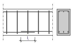
Fig. 7.1 Lab splice length in reinforced concrete.#
Cover#
Structural Element |
Cover c [mm] per environment |
Increase [mm] |
|||
|---|---|---|---|---|---|
dry |
wet |
salt or aggresive |
modified surface |
uninspected table surface |
|
Plaat en wand |
15 |
25 |
30 |
+5 |
+5 |
Balk, poer en console |
25 |
30 |
35 |
+5 |
+5 |
Kolom |
30 |
35 |
40 |
+5 |
+5 |
Note
Further demands:
c ≥ Ø (for bars ≤ Ø 25 mm)
c ≥ 1,5Ø (for bars > Ø 25 mm)
prestressing steel: + 5 mm
Under certain conditions it is allowed to bundle 2 of three bars together without spacing. These bundles can be regarded as a single bar with the same cross section (mm2 ) as the total bundle.
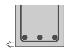
Fig. 7.2 Reinforced concrete cover.#
Minimal bar distances#
The spacing between (not c.t.c distance) the bars should be not less than the maximum of:
the bar diameter
the maximum aggregate size + 5 mm
20 mm
When bars are placed in separate layers, care must be taken that good compaction of the concrete must be possible. In the case of walls there must be enough room to cast concrete in the lower regions of the wall. At laps the distances between the bars may be smaller.
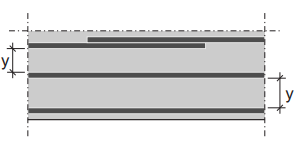
Fig. 7.3 Minimal bar distances in reinforced concrete.#