
10.8. Bridge beams#
Different fabricators offer prefabricated bridge beams. The beams are available in different shapes: box beams, I-sections and inverted T-sections. This section gives an overview of some possibilities 12.
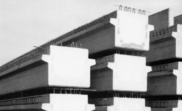
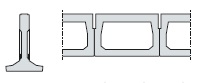
Fig. 10.39 Prefab concrete bridge beams.#
Applications#
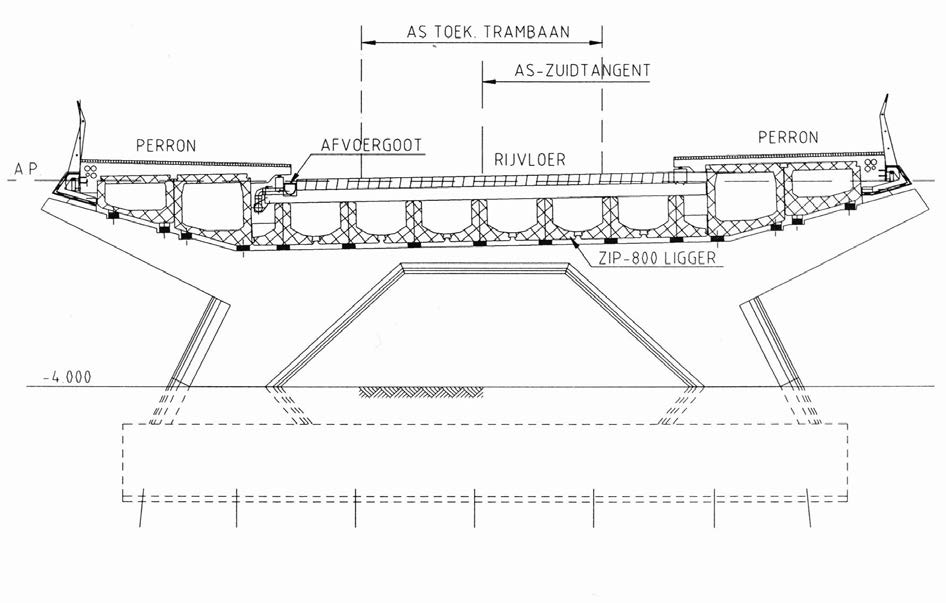
Fig. 10.40 Prefab beams with a compressive slab and a bridge deck, tram line construction.#
The curved viaduct of the tram line crossing the N201 is made from prefab beams with a compressive slab and a bridge deck. The viaduct is supported by pilars on foundation blocks with center to center distances of 20 meters. The foundation blocks are founded on prefab or Fundexpiles.
The pilars are cast in one piece with self compacting concrete because:
High concentrations of reinforcement occured.
Not all locations could be reached with compaction devices.
High erection speed was necessary
There was a large chance of the arisal of rockpockets which, even after repair, always have lower strength and druability.
Construction joints were not desirable from an aestethical point of view
Near the bus stop the bridge deck is built from ZIP-beams with a compressive layer of 250 mm and an additional deck layer of 200 mm. The decklayer does not contribute to the bearing capacity of the bridge. In the future it has to be possible to mill slots in the deck layer to place tramrails. The deck layer is connected to the compressive layer by means of hairpins. Also transverse and longitudinal reinforcement is applied, adjusted to the future tramrails.
Near the platforms the pillars are equipped with concrete consoles on which two boxbeams are placed to carry the platforms. The box beams are designed in such a way that in the event of bus loading on the platforms the structure will not be damaged. The box beams with a length of 20 m are placed on elastomeric bearings on the consoles. In the design only the platforms were detailed, while the bridge deck was only specified once every four spans, about 80 m. The bridge deck was specified minimally.
During the execution phase the design was re-evaluated and the details where further developed. This was now possible due to the extra information which had come available. Eventually a circular cross section has been developed, consisting of existing elements. This cross section could not be applied without integrating the bridge deck and platforms, while the pilars where already being casted. An additional structural check was necessary to, if necessary, adjust the design.
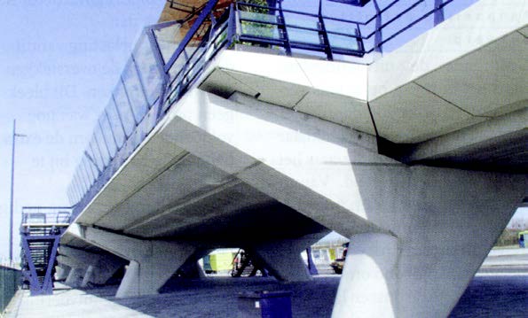
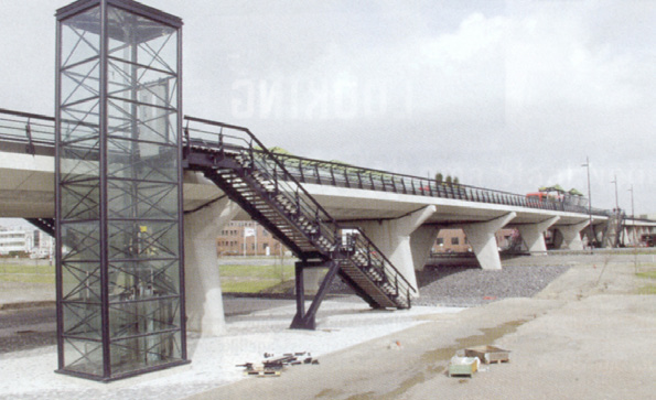
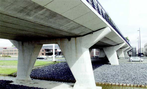
Fig. 10.41 Three different views on the tram line.#
Bridge beams I#
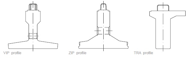
Fig. 10.42 Railbeam structures#
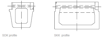
Fig. 10.43 Box beam structures#
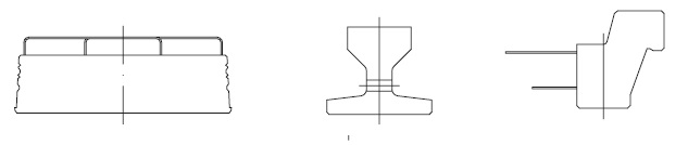
Fig. 10.44 Solid composite structures#
Bridge beams II#
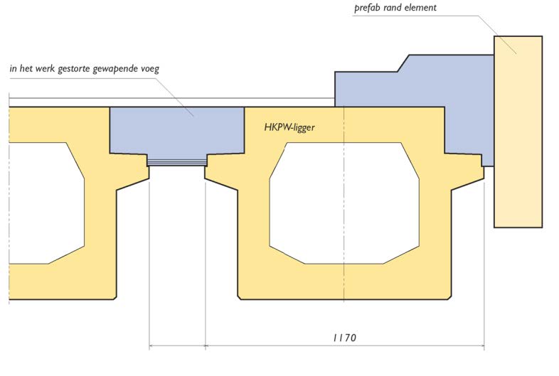
Fig. 10.45 HKPW profile#
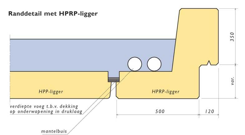
Fig. 10.46 HPRP profile#
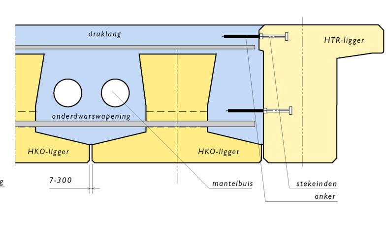
Fig. 10.47 HKO profile#
- 1
Haitsma.nl: Bridges, foundations, offices, parking lots. CAD details and design graphs.
- 2
Spanbeton.nl: Large prefab elements used in road- and railway construction, hydraulic engineering, industrial buildings, and concrete sheet piling.