
4.2. Architectural drawings#
For architects, the following three drawings of the structure are of most interest:
Exploded axonometric drawing#
Exploded axonometric drawing (also called Axo): In this, the structure can be seen in its entirety and the consistency with the architectural design can be conveyed. The stability of the structure can also be assessed. An example is given below. In the chapter drawing examples Axos of concrete, steel and timber supporting structures are given.
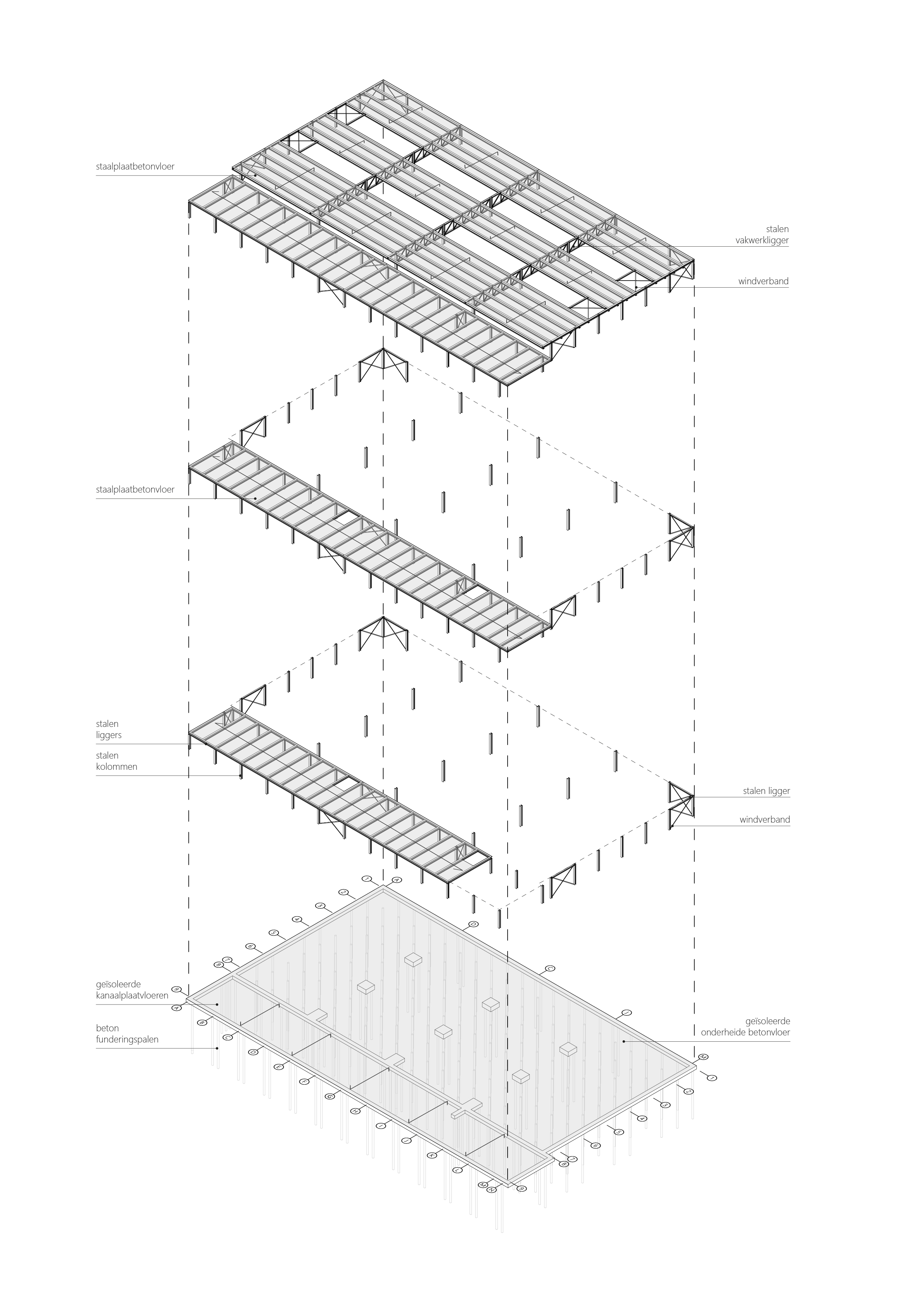
Fig. 4.12 Axonometric drawing example.#
Axonomentric drawing is an overview of the overall supporting structure. It provides insight into the spatial arrangement in both the horizontal and vertical planes. The vertical and horizontal force distribution of the structure is often easy to see from the Axo because all structural parts are given in a single view. The second important function of the Axo is to show how the supporting structure fits the architectural design intent.
Load-bearing structure floor plans#
Load-bearing (Draagconstructie) structure floor plans: These drawings show how vertical force transmission works in the building and contain more detailed information than the axonometric drawing such as materials dimensions, spans and profiles. An example is given below. In the chapter drawing examples load-bearing floor plans of concrete, steel and timber supporting structures are given.
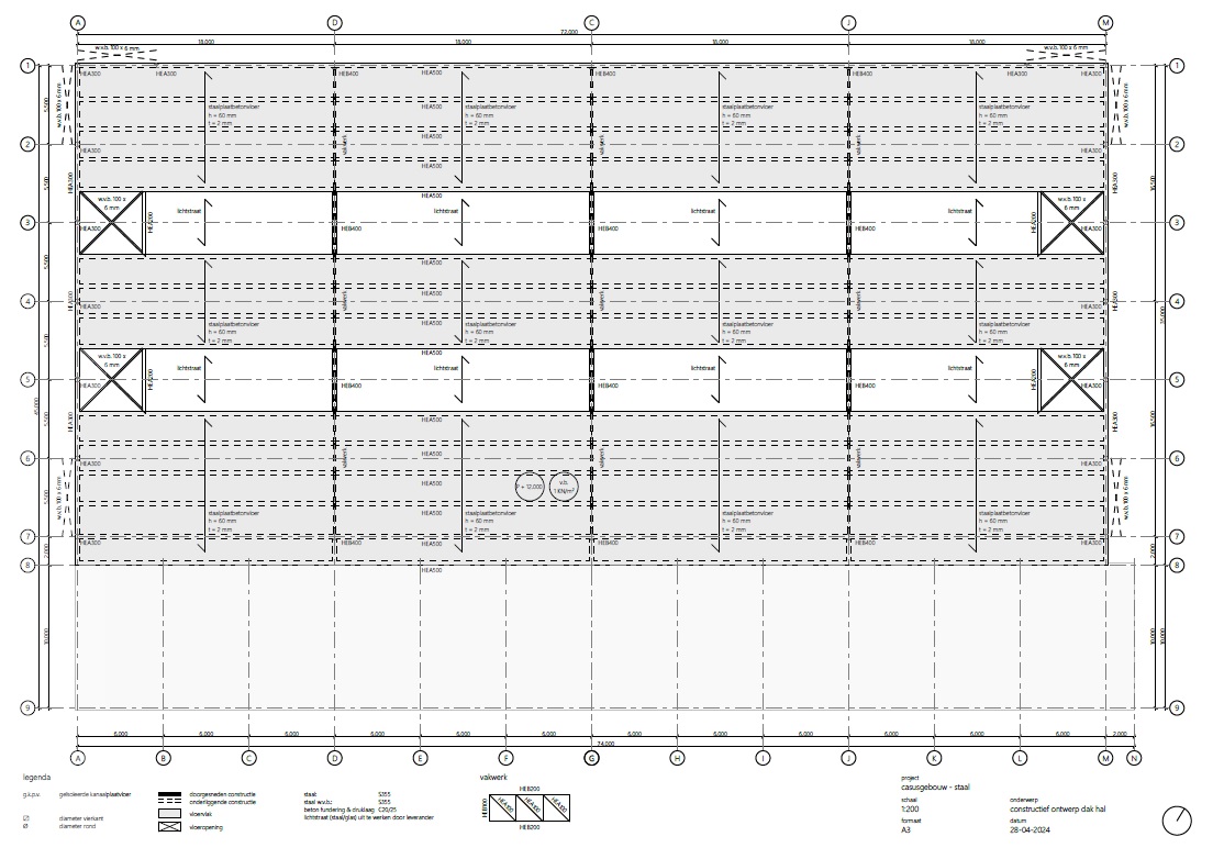
Fig. 4.13 Load-bearing structural floor plan example.#
In the supporting structure floor plan, we draw the structure through which we cut (at about 1 metre above the floor) as in a regular floor plan, with appropriate shading. However, the supporting structure floor plan is different from a regular floor plan because we also (mainly) draw the structure below the floor. Because we do not see these construction parts directly, we draw them with a dashed line. Often, for example, columns will be directly above each other, in which case we obviously don’t see the dashed line, because we draw the cut column above the floor with a continuous line.
Connection detail#
Connection detail: Here you draw only the structural parts. This can be in a 3D or a number of 2D drawings. Examples of drawings of connections can be found in the Structural Design Essentials. Standard joints of the various materials are given in the ‘Design’ section. You can either use these directly or adapt them according to the specific requirements of the joint. Joints can be very image-defining in a building. In such cases, it is important, as a designer, to pay attention to their design. In other cases, if the connection is not image-defining in the building, its design is often left to the structural engineer or contractor.