
11.9. Connections#
Cont. column-beam#
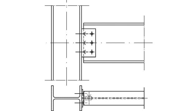
Fig. 11.20 Connection with bolted angles#
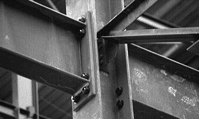
Fig. 11.21 Beam-column connection with endplate. The endplate is welded to the beam in the workshop and bolted to the column on site.#
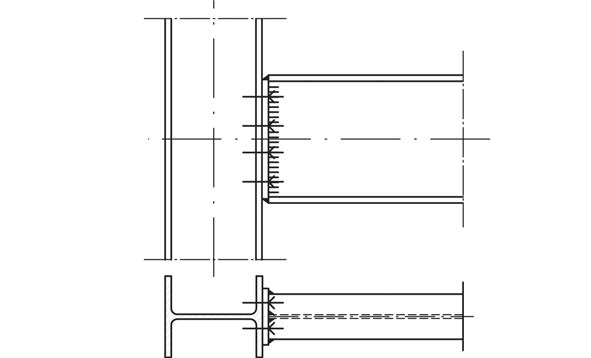
Fig. 11.22 Connection with welded enplate, bolted to column#
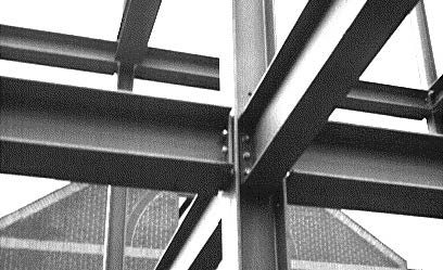
Fig. 11.23 Beam-column connection with bolted endplates. The beams are also connected to the web of the column.#
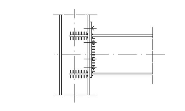
Fig. 11.24 Connection with elongated endplate, bolted to stiffened column#
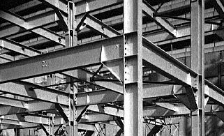
Fig. 11.25 A stiffened beam-column connection. This way a rigid steel frame is obtained. A plastic calculation is possible for these structures.#
Beam-beam#
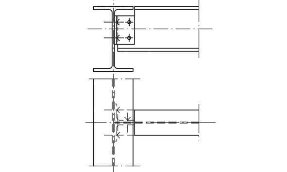
Fig. 11.26 Connection with bolted angles#
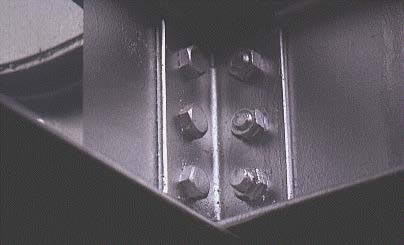
Fig. 11.27 Connection with bolted angles#
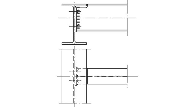
Fig. 11.28 Connection with welded endplate, bolted to other element#
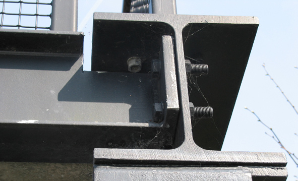
Fig. 11.29 Connection with welded endplate, bolted to other element#
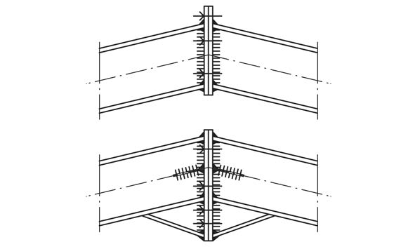
Fig. 11.30 Connection with elongated endplate, bolted to other (stiffened) element.#
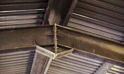
Fig. 11.31 Connection with elongated endplate, bolted to other (stiffened) element.#
Beam-wall#
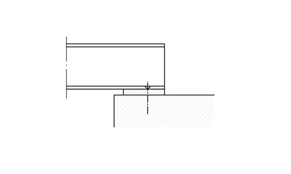
Fig. 11.32 Support on elastomer, with lock bolt.#
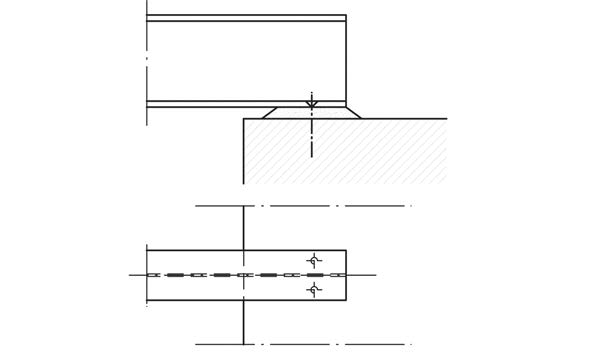
Fig. 11.33 Support on elastomer, with lock bolt.#
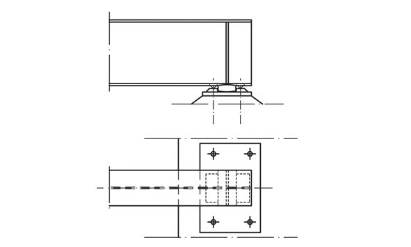
Fig. 11.34 Support with steel axle.#
Center-column-beam#
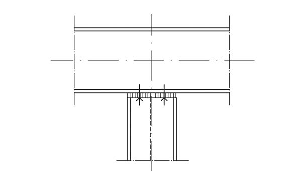
Fig. 11.35 Welded endplate with four bolts.#
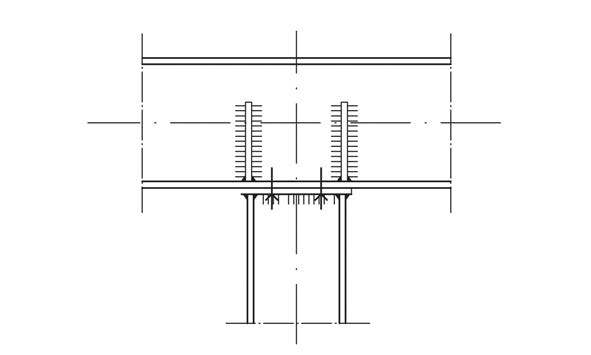
Fig. 11.36 Welded endplate with four bolts with welded stiffeners on beam web.#
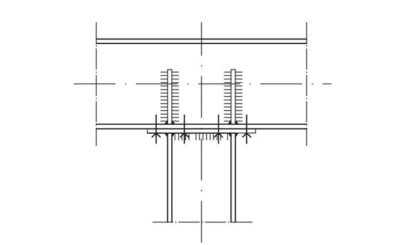
Fig. 11.37 Elongated welded endplate with eight bolts, welded stiffeners on beam web.#
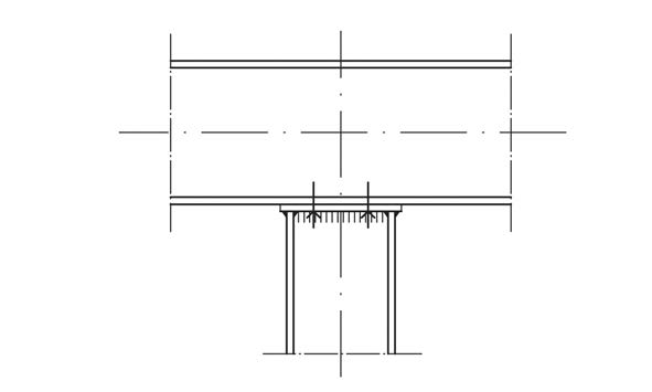
Fig. 11.38 Welded endplate with four bolts.#
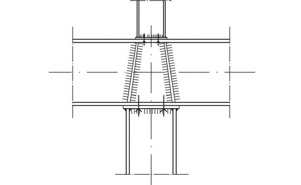
Fig. 11.39 Welded endplate with welded stiffeners on beam web.#
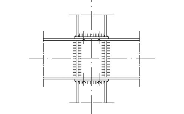
Fig. 11.40 Welded endplate with welded stiffeners on beam web.#
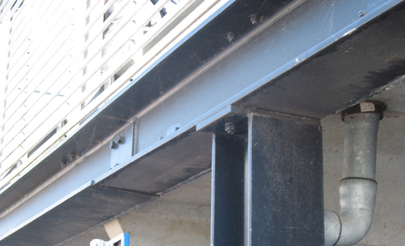
Fig. 11.41 Simple connection with welded endplate. During erection the beam is bolted into place (car park near Delft public library).#
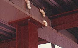
Fig. 11.42 Welded endplate with four bolts, placed outside the column section.#
Column-support#
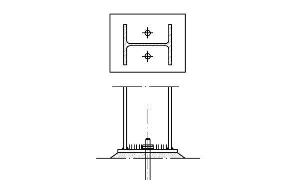
Fig. 11.43 Column support with welded endplate and a single row of bolts.#
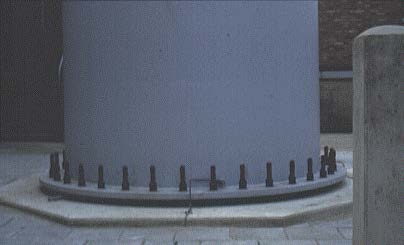
Fig. 11.44 Column support with welded endplate and a single row of bolts.#
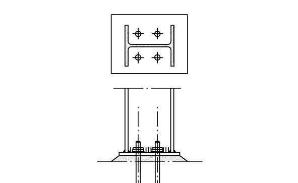
Fig. 11.45 Column support with welded endplate and four bolts.#
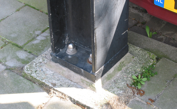
Fig. 11.46 Column support with welded endplate and four bolts.#
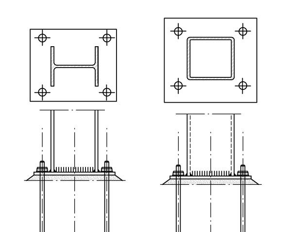
Fig. 11.47 Column support with bolts outside column section for extra stiffness.#
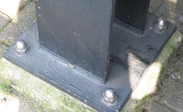
Fig. 11.48 Column support with bolts outside column section for extra stiffness.#
End column-beam#
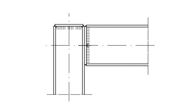
Fig. 11.49 Welded endplate with two bolts.#
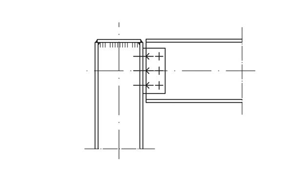
Fig. 11.50 Connection with bolted angles.#
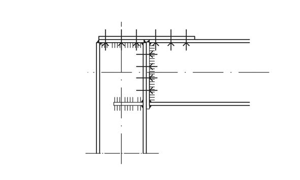
Fig. 11.51 Welded elongated endplate with top plate and stiffeners for extra stiffness.#
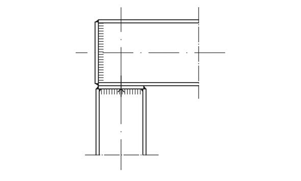
Fig. 11.52 Welded endplate with two bolts.#
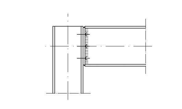
Fig. 11.53 Welded endplate with six bolts.#
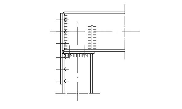
Fig. 11.54 Welded endplate with extra plate in tension zone and stiffeners.#
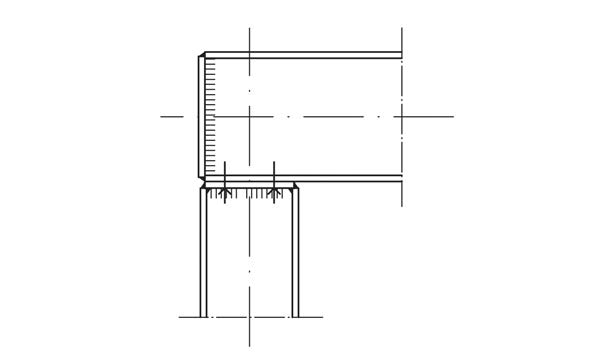
Fig. 11.55 Welded endplate with four bolts.#
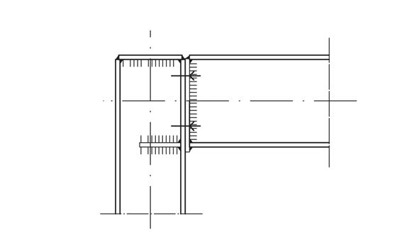
Fig. 11.56 Welded elongated endplate with four bolts and stiffeners.#
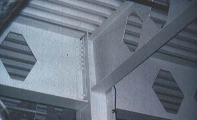
Fig. 11.57 Connection between castellated beam and column. Be aware of the reduced shear capacity of castellated beams.#
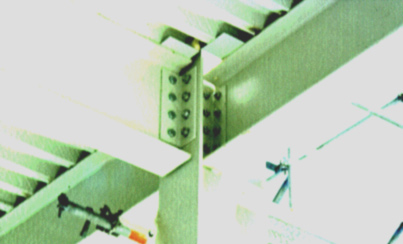
Fig. 11.58 Beam-column connection using bolted angles.#