
18.1. Pre-design of timber hall#
Note
The calculations serve as examples for educational purposes and not as guidance for practice.
Design example#
Design of “FLUX” type building
FLUX \(\rightarrow\) braced in one direction, unbraced in the other directions
This design: braced in two directions
With wind bracing
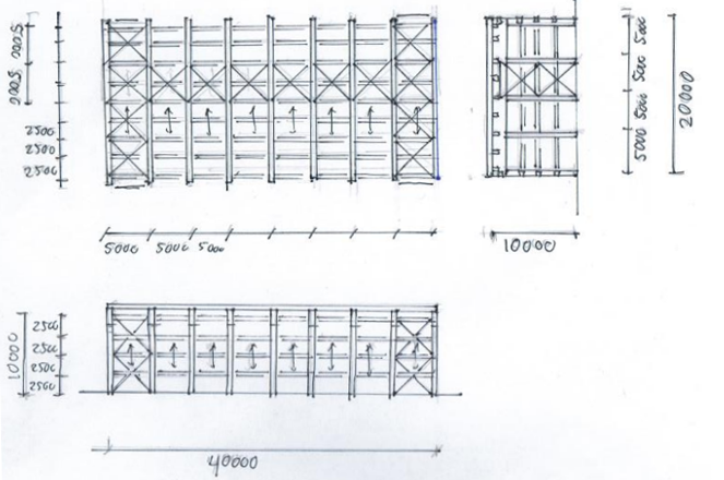
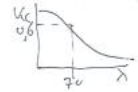
Fig. 18.1 Schematic drawing#
Material#
Laminated Timber Beams GL24h:#
\(f_{m;0;k} = 24 \, \text{N/mm}^2 \rightarrow f_{mod} = 24 \cdot 0.7 = 16.8 \, \text{N/mm}^2\)
\(f_{c;0;k} = 24 \, \text{N/mm}^2 \rightarrow f_{cod} = 24 \cdot 0.7 = 16.8 \, \text{N/mm}^2\)
\(E_{0;mean} = 11500 \, \text{N/mm}^2\)
\(k_{def} = 0.6 \, \text{for permanent loads}\)
Sawn Timber Beams C24:#
\(f_{m;0;k} = 24 \, \text{N/mm}^2 \rightarrow f_{mod} = 24 \cdot 0.7 = 16.8 \, \text{N/mm}^2\)
\(f_{c;0;k} = 21 \, \text{N/mm}^2 \rightarrow f_{cod} = 21 \cdot 0.7 = 14.7 \, \text{N/mm}^2\)
\(E_{0;mean} = 11000 \, \text{N/mm}^2\)
\(k_{def} = 0.6 \, \text{for permanent loads}\)
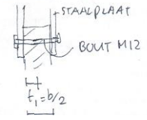
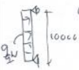
Fig. 18.2 Steel connection#
Connections#
Steel-to-Timber
Bolts M12 8.8
If \(t_{1} = \frac{b}{2} > 100 \, \text{mm}\), then \(F_{v;RK} = 10 \, \text{kN}\) per shear plane
Loads#
Permanent: Roof (structure + finish):
\(p_{roof;self-weight} = 0.5 \, \text{kN/m}^2 = p_{g}\)Variable: Snow and wind
\(p_{roof;snow} = 0.56 \, \text{kN/m}^2 = p_{q;sn} \ \ \ \left( \psi_{0} = 0 \right)\)
Area 2, \(h = 10 \rightarrow p_{wind} = 1.0 \, \text{kN/m}^2 = p_{q;w} \ \ \ \left( \psi_{0} = 0 \right)\)CC2 \(rightarrow \gamma_{q;g} = 1.2 \, (0.9 \, \text{if favourable}); \, \gamma_{q;q} = 1.5\)
Dimensioning of beams/columns based on rules of thumb#
Columns#
\(h_{y} = \frac{l_{buc;y}}{20} = \frac{10000}{20} = 500 \, \text{mm}\)
\(h_{z} = \frac{l_{buc;z}}{20} = \frac{5000}{20} = 250 \, \text{mm}\)
Note
\(l_{buc;z} = 5000\) due to wind bracing in the façade.
Main Beam (centre-to-centre 5000 mm):#
\(h = \frac{L}{17} = \frac{20000}{17} = 1176 \rightarrow \text{choose} \, 1200 \, \text{mm}\)
\(b = \frac{h}{6} = \frac{1200}{6} = 200 \rightarrow \text{choose} \, 250 \, \text{mm}\)
Note
\(b = \frac{h}{6}\) applies for laminated timber; 250 mm is chosen as it matches the column dimension.
Purlins (centre-to-centre 2500 mm):#
\(h = \frac{L}{17} = \frac{5000}{17} = 294 \rightarrow \text{choose} \, 300 \, \text{mm}\)
\(b = \frac{h}{3} = \frac{300}{3} = 100 \rightarrow \text{choose} \, 100 \, \text{mm}\)
Note
\(b = \frac{h}{3}\) applies for sawn timber; choose the thickness of façade panels based on the centre-to-centre spacing of the purlins, i.e., 2500 mm.
Bearing of Main Beams on Columns: Fork Supports#
No rotation about the x-axis. Top chord supported by purlins to prevent lateral-torsional buckling due to snow load (compression at the top of the beam). For wind suction, buckling length: 20 m! (compression at the bottom, check lateral-torsional buckling during the verification phase).
Design verification for bending/compression and deformations#
Main beam (centre-to-centre 5 m)#
\(q_{\gamma} = 5 \cdot 0.5 = 2.5 \, \text{kN/m}\)
\(q_{q;sn} = 5 \cdot 0.56 = 2.8 \, \text{kN/m}\)
\(q_{d} = 1.2 \cdot 2.5 + 1.5 \cdot 2.8 = 7.2 \, \text{kN/m}\)
\(M_{d} = \frac{1}{8} \cdot 7.2 \cdot 20^2 = 360 \, \text{kNm}\)
\(\sigma_{mod} = \frac{360 \cdot 10^6}{\frac{1}{6} \cdot 250 \cdot 1200^2} = 6.0 \, \text{N/mm}^2 \rightarrow f_{mod} < 16.8 \, \text{OK}\)
\(\delta_{q;\gamma} = \frac{5 \cdot 2.5 \cdot 20000^4}{384 \cdot 11500 \cdot \frac{1}{12} \cdot 250 \cdot 1200^3} = 12.6 \, \text{mm}\)
Creep (only for permanent load) \(\rightarrow \delta_{q;\gamma;creep} = 0.6 \cdot 12.6 = 7.5 \, \text{mm}\)
\(\delta_{q;sn} = \frac{2.8}{2.5} \cdot 12.6 = 14 \, \text{mm}\)
\(\delta_{tot} = 12.6 + 7.5 + 14.0 = 34.1 \, \text{mm} < 0.004 \cdot 20000 = 80 \, \text{mm}\)
Optimisation#
\(W_{req} = W \cdot \frac{6.0}{16.8} = \frac{1}{6} \cdot 250 \cdot 1200^2 \cdot \frac{6.0}{16.8} = 2.1 \cdot 10^7 = \frac{1}{6} \cdot b \cdot h^2\)
\(h_{req} = \sqrt{\frac{2.1 \cdot 10^7 \cdot 6}{250}} = 717 \, \text{mm}\)
\(I_{req} = I \cdot \frac{34.1}{80} = \frac{1}{12} \cdot 250 \cdot 1200^3 \cdot \frac{34.1}{80} = 1.54 \cdot 10^{10} = \frac{1}{6} \cdot b \cdot h^3\)
\(h_{req} = \sqrt{\frac{1.54 \cdot 10^{10} \cdot 12}{250}} = 903 \, \text{mm} \, \leftarrow \text{governing}\)
\(\rightarrow \text{Choose } b \times h: \, 250 \times 1000\)
Column#
Effective length#
Verification of compressive stress
\(N_{d} = \left( 5 \cdot 10 \right) \cdot \left( 1.2 \cdot 0.5 + 1.5 \cdot 0.56 \right) = 72 \, \text{kN}\)
\(\lambda = \frac{l_{buc}}{i} \rightarrow i = 0.29 \cdot h \, \text{(rectangular cross-section)}\)
\(i_{z} = 0.29 \cdot 250 = 72.5 \, \text{mm}; \, l_{buc,z} = 5000 \, \text{mm} \rightarrow \frac{l_{buc,z}}{i_{z}} = 69\)
\(i_{y} = 0.29 \cdot 500 = 145 \, \text{mm}; \, l_{buc,y} = 10000 \, \text{mm} \rightarrow \frac{l_{buc,y}}{i_{y}} = 69 \rightarrow k_{c} = 0.6\)
\(\sigma_{c;0;d} = \frac{72 \cdot 10^3}{250 \cdot 500} = 0.6 \, \text{N/mm}^2 << 0.6 \cdot 16.8 = 10.1 \, \text{N/mm}^2\)
Windload#
Control deformation:
\(q_{w;d} = 5.0 \cdot 1.0 \cdot \left( 0.8 + 0.3 \right) \cdot 1.5 = 8.3 kN/m\)
\(M_{d} = \frac{1}{8} \cdot 8.3 \cdot 10^2 = 103 kNm\)
\(\sigma_{mod} = \frac{103 \cdot 10^6}{\frac{1}{6} \cdot 250 \cdot 500^2} = 9.9 N/mm^2 < 16.8 \ OK\)
\(\delta = \frac{5 \cdot 1.0 \cdot \left(0.8 + 0.3\right) \cdot 10000^4}{384 \cdot 11500 \cdot \left(\frac{1}{12} \cdot 250 \cdot 500^3\right)} = 23.9 mm < 0.004 \cdot 10000 = 40 mm \ OK\) \
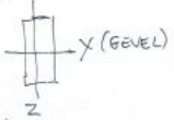
Connection column-beam#
Windsuction#
\(N_{d} = \left( 5 \cdot 10 \right) \cdot \left( -0.9 \cdot 0.5 + 1.5 \cdot 1.0 \cdot \left( 0.7 + 0.3 \right) \right) = 52.5 \, \text{kN}\)
Note
Surface area: \(5 \cdot 10\)
Favourable self-weight: \(-0.9\)
\(\gamma_{g} = 1.5\)
\(\gamma_{q} = 1.0\)
Wind factors: \(\left( 0.7 + 0.3 \right)\)
Required number of shear planes with bolds
M12 steel-to-timber: \(\frac{52.5}{7} = 7.5 = 8\) shear plane
1 shear plane: \(F_{vd} = 10 \cdot 0.7 = 7 kN\)
\(\rightarrow\) 4 bolts x 2 shear planes
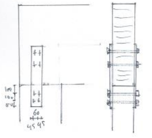
Fig. 18.3 Drawing of connection.#
Verification of deformation in roof wind bracing#
\(I_{eff} = \Sigma \ z^2 \cdot A \cdot \gamma = 2 \cdot 2500^2 \cdot \left(250 \cdot 5000 \right) \cdot 0.5 = 7.82 \cdot 10^{11} mm^2\)
Note
Only the Steiner component is considered for \(I_{eff}\)
\(\gamma\) is a reduction factor for deformation of the wall members and connections.
\(q_{wind} = (\frac{1}{2})[(\frac{10}{2}) \cdot (0.8 + 0.4) + (0.04 \cdot 40)]\cdot 1 = \frac{1}{2} \cdot 7.6 \cdot 1.0 = 3.8 kN/m\)
Note
\(\frac{1}{2}\): 2 Horizontal trusses
\(\frac{10}{2}\): Half transferred to foundation
\(0.8\): Pressure on front façade
\(0.4\): Suction on rear façade
Wind friction on roof: \(0.04\)
\(q_{w} = 1.0\)
\(S = \frac{5}{384} \cdot \frac{3.8 \cdot 200000^4}{11500 \cdot 7.82 \cdot 10^{11}} = 0.9 mm << \frac{l}{500} = 20000/500 = 40 mm\)
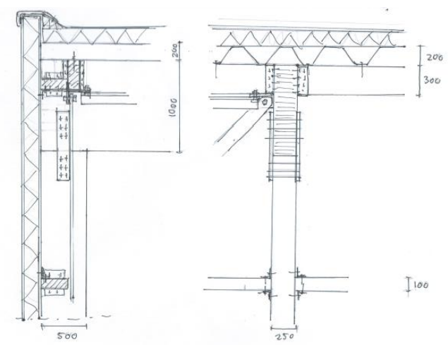
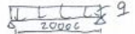
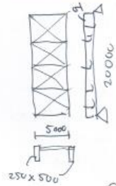
Fig. 18.4 Sketch of timber hall#