
11.2. Rules of thumb#
These ‘rules of thumb’ (Dutch: ‘vuistregels’) are to be seen as a quick way to estimate dimensions of structural members, based on span \(L\) and/or center-to-center spacing \(s\). These estimated dimensions should only serve as input for an early design stage calculation (e.g. first check of capacity or deformation), after which you will use more advanced design rules (e.g. Eurocode) for a more accurate calculation. Mind that you should not use them the other way around, as if the rules of thumb were some law that should be respected. They are just meant to get your design started.
Steel columns#
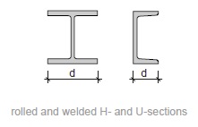
Fig. 11.2 Rolled and welded H- and U-sections#
Rules of thumb
single storey:
\(h_{st} = 2\) to \(8\) m
\(d = h_{st}/25\) to \(h_{st}/20\)
multi storey:
\(h_{st} = 2\) to \(4\) m
\(d = h_{st}/18\) to \(h_{st}/7\)
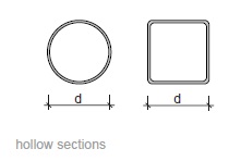
Fig. 11.3 Hollow sections#
Rules of thumb
single storey:
\(h_{st} = 2\) to \(8\) m
\(d = h_{st}/35\) to \(h_{st}/20\)
multi storey:
\(h_{st} = 2\) to \(4\) m
\(d = h_{st}/28\) to \(h_{st}/7\)
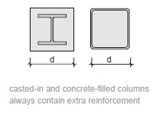
Fig. 11.4 Cast-in and concrete-filled columns always contain extra reinforcement#
Rules of thumb
\(h_{st} = 2\) to \(4\) m
\(d = h_{st}/15\) to \(h_{st}/6\)
Main floorbeams#
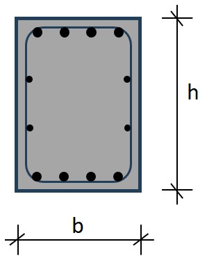
Fig. 11.5 Wide flange (H) sections and hollow sections.#
Rules of thumb
\(L = 4\) to \(12\) m
\(h = 100\) to \(500\) mm
\(h = L/28\) to \(L/18\)
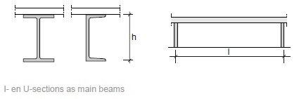
Fig. 11.6 I- and U-sections as main beams.#
Rules of thumb
\(L = 6\) to \(30\) m
\(h = 200\) to \(500\) mm
\(h = L/20\) to \(L/15\)
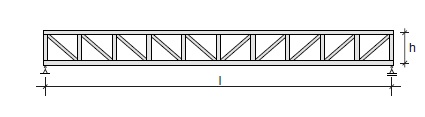
Fig. 11.7 Truss beam.#
Rules of thumb
\(L = 12\) to \(45\) m
\(h = 1000\) to \(4000\) mm
\(h = L/15\) to \(L/8\)
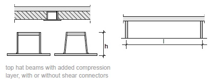
Fig. 11.8 Top hat beams with added compression layer, with or without shear connections.#
Rules of thumb
\(L = 7\) to \(15\) m
\(h = 300\) to \(1000\) mm
\(h = L/25\) to \(L/20\)
Floors#
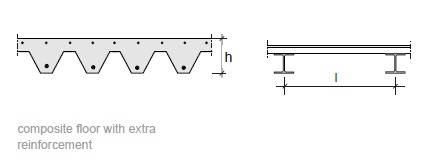
Fig. 11.9 Composite floor with extra reinforcement.#
Rules of thumb
\(L = 2\) to \(4\) m
\(h = 100\) to \(150\) mm
\(h = L/30\) to \(L/25\)
Main roofbeams#
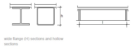
Fig. 11.10 Wide flange (H) sections and hollow sections.#
Rules of thumb
\(L = 6\) to \(14\) m
\(h = 100\) to \(500\) mm
\(h = L/30\) to \(L/20\)
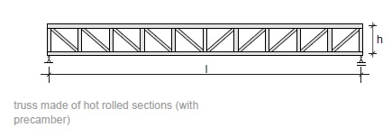
Fig. 11.11 Truss made of cold formed sections.#
Rules of thumb
\(L = 12\) to \(75\) m
\(h = L/18\) to \(L/10\)
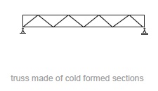
Fig. 11.12 Truss made of formed sections.#
Rules of thumb
\(L = 5\) to \(28\) m
\(h = 300\) to \(1000\) mm
\(h = L/25\) to \(L/15\)
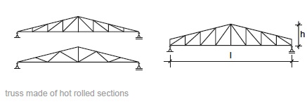
Fig. 11.13 Truss made of hot rolled sections#
Rules of thumb
\(L = 8\) to \(20\) m
\(h = 300\) to \(1000\) mm
\(h = L/10\) to \(L/5\)
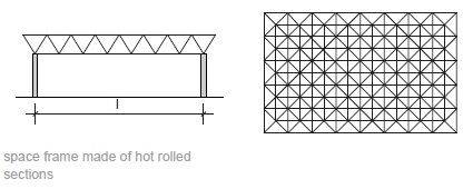
Fig. 11.14 Space frame made of hot rolled sections.#
Rules of thumb
\(L = 30\) to \(150\) m
\(h = L/30\) to \(L/15\)
Purlins roofstructures#
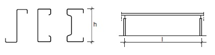
Fig. 11.15 Steel purlin roofstructure.#
Rules of thumb
\(L = 3\) to \(12\) m
\(h = 120\) to \(300\) mm
\(h = L/35\) to \(L/25\)
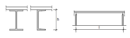
Fig. 11.16 Steel purlins roofstructure.#
Rules of thumb
\(L = 6\) to \(40\) m
\(h = 200\) to \(1000\) mm
\(h = L/26\) to \(L/18\)
Roofing plates#
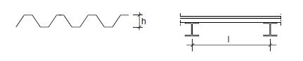
Fig. 11.17 Cold formed corrugated steel roofing plate.#
Rules of thumb
\(L= 2\) to \(6\) m
\(h = 25\) to \(120\) mm
\(h = L/70\) to \(L/40\)
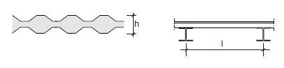
Fig. 11.18 Cold formed corrugated steel sandwich panel with foam core.#
Rules of thumb
\(L = 2\) to \(3\) m
\(h = 75\) to \(150\) mm
\(h = L/30\) to \(L/25\)