
12.2. Rules of thumb and details#
These ‘rules of thumb’ (Dutch: ‘vuistregels’) are to be seen as a quick way to estimate dimensions of structural members, based on span \(L\) and/or center-to-center spacing \(s\). These estimated dimensions should only serve as input for an early design stage calculation (e.g. first check of capacity or deformation), after which you will use more advanced design rules (e.g. Eurocode) for a more accurate calculation. Mind that you should not use them the other way around, as if the rules of thumb were some law that should be respected. They are just meant to get your design started.
Straight beam (possibly with precamber)#
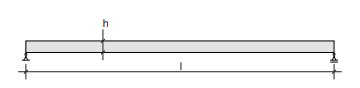
Fig. 12.2 Straight beam (possibly with precamber).#
Rules of thumb
Solid timber beams
\(L = 2\) to \(6\) m
\(h = \frac{L}{20}\) to \(\frac{L}{15}\) m
Glulam (=glue-laminated) beams
\(L = 6\) to \(30\) m
\(s < 5\) m \(\rightarrow h = \frac{L}{17}\) (\(s\) = center-to-center spacing of beams)
\(s = 5\) to \(8\) m \(\rightarrow h = \frac{l}{16}\)
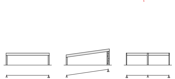
Fig. 12.3 Possible shapes.#
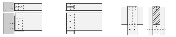
Fig. 12.4 Details (left: support on continuous column; middle: support on concrete wall; right: support on double timber column (by means of support block)).#
Straight beam (possibly with cantilever)#
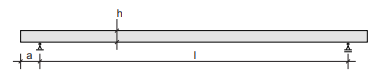
Fig. 12.5 Straight beam (possibly with cantilever).#
Rules of thumb
Glulam beams
\(L = 30\) m
\(s = 3.6\) to \(5.4\) m
\(a = 0.25 \cdot L \rightarrow h = \frac{L}{21}\) to \(\frac{L}{16}\)
\(s = 3\) to \(5\) m (\(s\) = center-to-center spacing of beams)
\(a = 0.4 \cdot L \rightarrow h = \frac{L}{24}\) to \(\frac{L}{18}\)
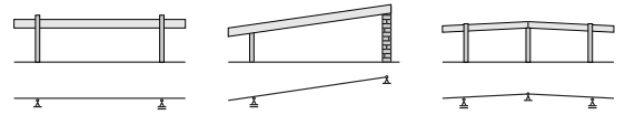
Fig. 12.6 Possible shapes.#
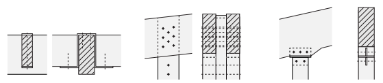
Fig. 12.7 Details (left: support of purlins on main beam by means of Z-profile; middle: double beam on a double timber column (bolted); right: beam on timber column, with steel connector plate (bolted)).#
Saddle roof with inclined upper edge#
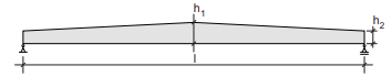
Fig. 12.8 Saddle roof with inclined upper edge.#
Rules of thumb
Glulam beam
\(L = 6\) to \(30\) m
\(h_1 = \frac{L}{18}\) to \(\frac{L}{14}\)
\(h_2 = \frac{L}{22}\) to \(\frac{L}{18}\)
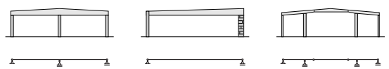
Fig. 12.9 Possible shapes.#
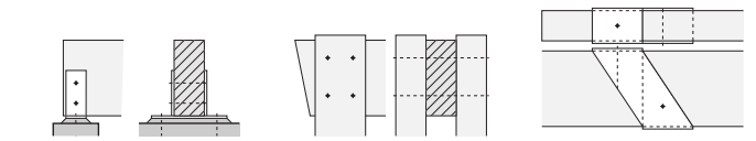
Fig. 12.10 Details (left: beam on wall, welded steel connection; middle: connection between beam and double column (bolted); right: beam-beam connection with steel connector plate (Dutch: gerberligger)).#
Saddle roof with inclined or curved upper and lower edge#
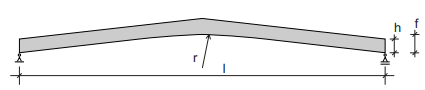
Fig. 12.11 Saddle roof with inclined or curved upper and lower edge.#
Rules of thumb
Glulam beams
\(L = 7\) to \(40\) m
\(s = 5\) to \(7 m \rightarrow h = \frac{L}{18}\) to \(\frac{L}{14}\) (\(s\) = center-to-center spacing of beams)
\(f = \frac{L}{10}\) to \(\frac{L}{5}\)
\(r \geq 6\) m
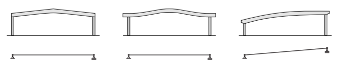
Fig. 12.12 Possible shapes.#
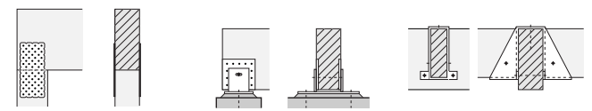
Fig. 12.13 Details (left: beam-column connection (nailed plates); middle: support on wall, full hinge with slotted hole (screwed steel plate); right: purlin-beam connection with steel connector, load acts on top of main beam).#
The upper edges need lateral support.
Warning
The curved shape causes tension pependicular to the grain.
Continuous beams#
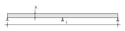
Fig. 12.14 Continuous beam.#
Rules of thumb
Glulam beams
\(L = 6\) to \(30\) m
\(s < 5\) m \(\rightarrow h = \frac{L}{34}\) (\(s\) = center-to-center spacing of beams)
\(s = 5\) to \(8\) m \(\rightarrow h = \frac{L}{30}\)
Glulam trusses
\(L = 10\) to \(80\) m
\(s = 2\) to \(5\) m \(\rightarrow h = \frac{L}{18}\) to \(\frac{L}{16}\)
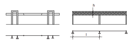
Fig. 12.15 Possible shapes.#
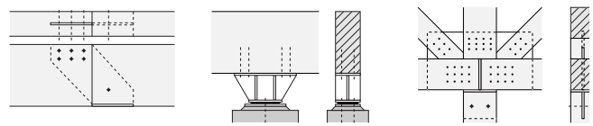
Fig. 12.16 Details (left: beam-beam connection with steel connector plate; middle: heavy support (welded); right: truss connection (with column) wih coupler plate and dowels).#
The upper edges need lateral support.
Straight truss#
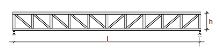
Fig. 12.17 Straight truss.#
Rules of thumb
Solid timber
\(L = 5\) to \(25\) m
\(s = 2.5\) to \(6\) m \(\rightarrow h = \frac{L}{14}\) to \(\frac{L}{10}\) (\(s\) = center-to-center spacing of trusses)
Glulam
\(L = 20\) to \(80\) m
\(s = 2.5\) to \(6\) m \(\rightarrow h = \frac{L}{15}\) to \(\frac{L}{10}\)
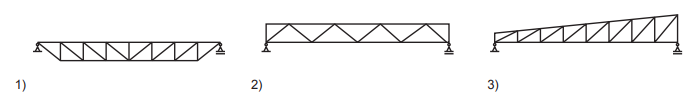
Fig. 12.18 Possible shapes.#
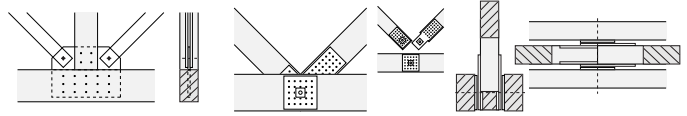
Fig. 12.19 Details (left: connection of tensile bars (steel strips) to bottom chord and compressive strut (coupler plate); middle: connection between bottom chord and diagonals with screwed steel plates and central axle; right: connection between bottom chord and diagonals with screwed steel plates and central axle).#
The upper chords (under compression) must be supported laterally in all trusses. For truss type 1 the bottom chord also needs lateral support to prevent the tensile chord from twisting out of plane.
Triangular or trapezoidal truss#
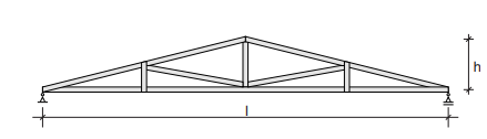
Fig. 12.20 Triangular or trapezoidal truss.#
Rules of thumb
Glulam beam
\(L = 7.5\) to \(30\) m
\(s = 4\) to \(10\) m \(\rightarrow h = \frac{L}{10}\) (\(s\) = center-to-center spacing of trusses)
Glulam saddle roof
\(l = 7.5\) to \(30\) m
\(s = 4\) to \(10\) m \(\rightarrow h = \frac{L}{12}\)
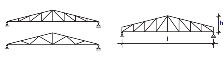
Fig. 12.21 Possible shapes.#
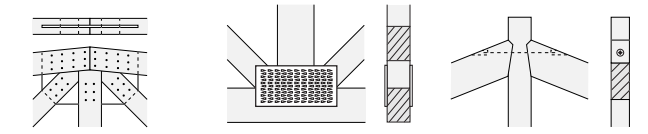
Fig. 12.22 Details (left: connection of upper chord, diagonals and vertical with coupler plate; middle: connection of bottom chord, diagonals and vertical with toothed plate; right: connection of upper chord and vertical with carpentry joint).#
The upper chords need lateral support.
Under stressed beam#
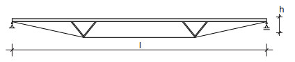
Fig. 12.23 Under stressed beam.#
Rules of thumb
Glulam beam
\(L = 8\) to \(80\) m
\(h = \frac{L}{20}\) to \(\frac{L}{15}\)

Fig. 12.24 Possible shapes.#
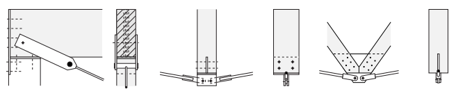
Fig. 12.25 Details (left: connection of the tensile bar at the support; middle: connection of the tensile bars and compressive strut with welded plates; right: connection of the tensile bars and diagonals with dowels).#
The upper edges need lateral support. The tensile bars also need lateral support to prevent twisting out of plane.
Rigid frame#
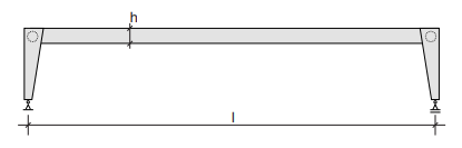
Fig. 12.26 Rigid frame.#
Rules of thumb
Glulam beam
\(L = 10\) to \(40\) m
\(s = 4\) to \(8\) m (\(s\) = center-to-center spacing of frames)
\(h = \frac{L}{20} - \frac{L}{15}\)
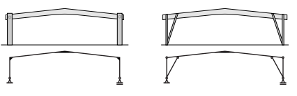
Fig. 12.27 Possible shapes.#
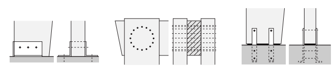
Fig. 12.28 Details (left: column-floor support with angle profiles and welded endplate (bolted); middle: moment resisting joint between double column and beam (dowels); right: column-floor support with cast-in plates (bolted)).#
This floor support connection is only suitable for low horizontal forces.
Three hinged frame (straight legs)#

Fig. 12.29 Three hinged frame (straight legs).#
Rules of thumb
Glulam beams, no tensile bar
\(L = 10\) to \(50\) m
\(f = \frac{L}{3}\)
\(s = 5\) to \(8\) m (\(s\) = center-to-center spacing of frames)
\(h = \frac{L}{50}\) to \(\frac{L}{30}\)
Glulam beams, with tensile bar
\(L = 15\) to \(50\) m
\(f = \frac{L}{6}\)
\(s = 5 - 8\) m
\(h = \frac{L}{50}\) to \(\frac{L}{30}\)
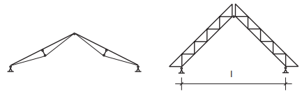
Fig. 12.30 Possible shapes.#
Rules of thumb
\(L = 15\) to \(50\) m
\(s = 5\) to \(8\) m (\(s\) = center-to-center spacing of frames)
\(h = \frac{L}{25}\) to \(\frac{L}{15}\)
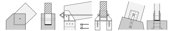
Fig. 12.31 Details (left: simple support, concrete footing with elastomeric bearing; middle: connection of double tensile bar to double column; right: column support on concrete footing with cast in plates (screwed)).#
This floor support connection is only suitable for low horizontal forces.
Three hinged frame (curved/kinked legs)#
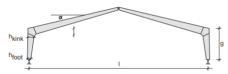
Fig. 12.32 Three hinged frame (curved/kinked legs).#
Rules of thumb
Frame with kinked corners
\(L = 15\) to \(50\) m
\(\alpha = 20 ^{\circ}\)
\(s = 4\) to \(5\) m \(\rightarrow h_{kink} = \frac{L + g}{28}\) and \(h_{foot} = 0.4 \cdot h_{kink}\)
\(s = 5\) to \(9\) m \(\rightarrow h_{kink} = \frac{L + g}{24}\) and \(h_{foot} = 0.4 \cdot h_{kink}\)
(\(s\) = center-to-center spacing of frames)
Frame with bent corners
\(L = 15\) to \(50\) m
\(r = 3.5\) to \(5\) m
\(\alpha = 20 ^{\circ}\)
\(s = 4\) to \(5\) m \(\rightarrow h_{kink} = \frac{L + g}{31}\) and \(h_{ridge} = 0.5 \cdot h_{kink}\) and \(h_{foot} = 0.67 \cdot h_{kink}\)
\(s = 5\) to \(9\) m \(\rightarrow h_{kink} = \frac{L + g}{26}\) and \(h_{ridge} = 0.5 \cdot h_{kink}\) and \(h_{foot} = 0.67 \cdot h_{kink}\)
(\(s\) = center-to-center spacing of frames)
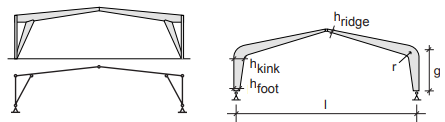
Fig. 12.33 Possible shapes.#
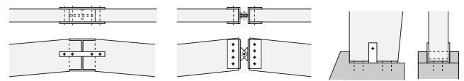
Fig. 12.34 Details (left: ridge connection with tensile connection and moulded I-profile; middle: ridge connection (bolted); right: support on concrete footing with welded steel plate).#
This floor support connection is only suitable for low horizontal forces.
Arch (solid and truss beam)#
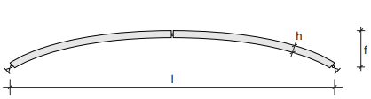
Fig. 12.35 Arch (solid and truss beam).#
Rules of thumb
Glulam beam
\(L = 20\) to \(100\) m
\(f = \frac{L}{7}\) to \(\frac{L}{5}\)
\(s = \le 5\) m \(\rightarrow h = \frac{L}{45}\)
\(s = 5\) to \(9\) m \(\rightarrow h = \frac{L}{40}\)
Glulam truss
\(L = 50\) to \(120\) m
\(f = \frac{L}{8}\) to \(\frac{L}{5}\)
\(s = 5\) to \(10\) m
\(h = \frac{L}{40}\) to \(\frac{L}{20}\)
(\(s\) = center-to-center spacing of arches)
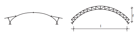
Fig. 12.36 Possible shapes.#
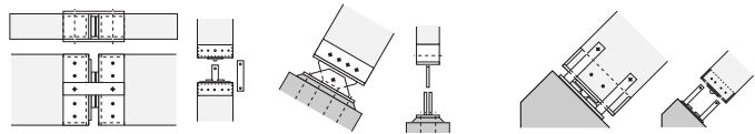
Fig. 12.37 Details (left: ridge connection with steel connectors (dowel); middle: support of arch (welded steel hinge); right: arch support).#